Configurable smart utility meter box

a smart and utility meter technology, applied in the direction of non-electric variable control, volume metering, instruments, etc., can solve the problems of accidental or intentional back injury, injury and terror, and injury to those who use such water

Inactive Publication Date: 2011-02-01
PARRIS EARL H +1
View PDF19 Cites 79 Cited by
  • Summary
  • Abstract
  • Description
  • Claims
  • Application Information

AI Technical Summary

Benefits of technology

[0018]Still another general object of the invention is to provide for a remote module configure to provide a resource customer (1) with access to the smart container data, (2) with a way of securely purchasing a unit of resource, (3) a way to securely pay a monthly bill, and (4) a way to remotely turn off resource flow at the meter box.

Problems solved by technology

First, municipalities often require water companies to protect the municipal water supply from contamination resulting from black flow.
While such schemes work well for preventing accidental back flow from the customer to utility service line, it does not address the accidental or intentional back flow of a substance into the utility main service line from a source intentionally connected to the input normally associated with a water meter.
Unfortunately, we live in an era when there are those among us that may disconnect a water meter and intentionally pump a substance into the utility service line with the intention of causing injury and terror.
Such a person could disconnect her water meter and pump a poison that can tolerate the chemicals in the water long enough to contaminate the school's water supply thereby causing injury to those who use such water.
However, the United States is still vulnerable to waterborne disease outbreaks, as demonstrated by the 1993 Milwaukee Cryptosporidium outbreak.
Additionally, while disinfection (or the inactivation of infectious organisms) will continue to be a critical element of drinking water treatment, recent research confirms that disinfection can create health risks from disinfectant residuals and disinfection byproducts (DBPs).
Depending on the placement of the sensor, the presence of chlorine may signify a leak.

Method used


Image

  • Configurable smart utility meter box
  • Configurable smart utility meter box
  • Configurable smart utility meter box

Examples


Embodiment Construction

[0092]Reference now will be made in detail to the embodiments of the invention, one or more examples of which are set forth below. Each example is provided by way of explanation of the invention, not limitation of the invention. In fact, it will be apparent to those skilled in the art that various modifications and variations can be made in the present invention without departing from the scope or spirit of the invention. For instance, features illustrated or described as part of one embodiment can be used on another embodiment to yield a still further embodiment. Thus, it is intended that the present invention covers such modifications and variations as come within the scope of the appended claims and their equivalents. Other objects, features, and aspects of the present invention are disclosed in or may be determined from the following detailed description. Repeat use of reference characters is intended to represent same or analogous features, elements or steps. It is to be unders...


PUM


Abstract

The invention relates to a meter box for housing a utility meter and configured for associating a customer service line to a utility service line. The meter box may be configured to fit within an existing meter box and may be configured with side sections in a telescopic arrangement. Flow control components at an input of the meter box prevent backflow.The meter box comprises an electronic module that includes a variety of selectable features including datalogging, AMR, environmental monitoring, and resource monitoring. A remote monitor is provided for allowing a customer to view selected data including consumption data, pressure, pH, temperature, warnings, remote turnoff, and provide secured bill paying services. Imaging / audio components provide visual and audio data which may include an image of an analog readout for a meter register, images of the metering environment, and sound data for metering environment.

Description

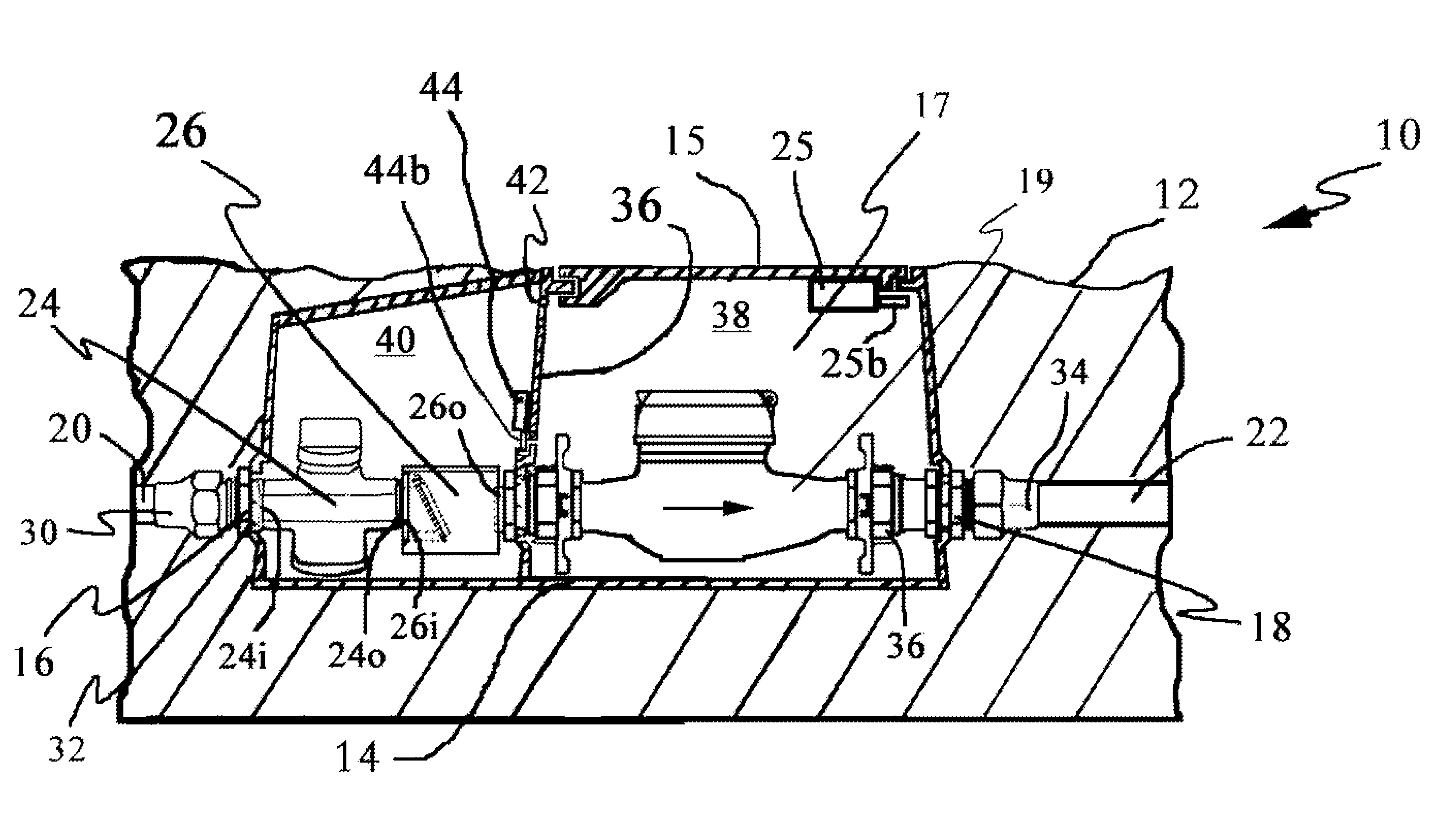
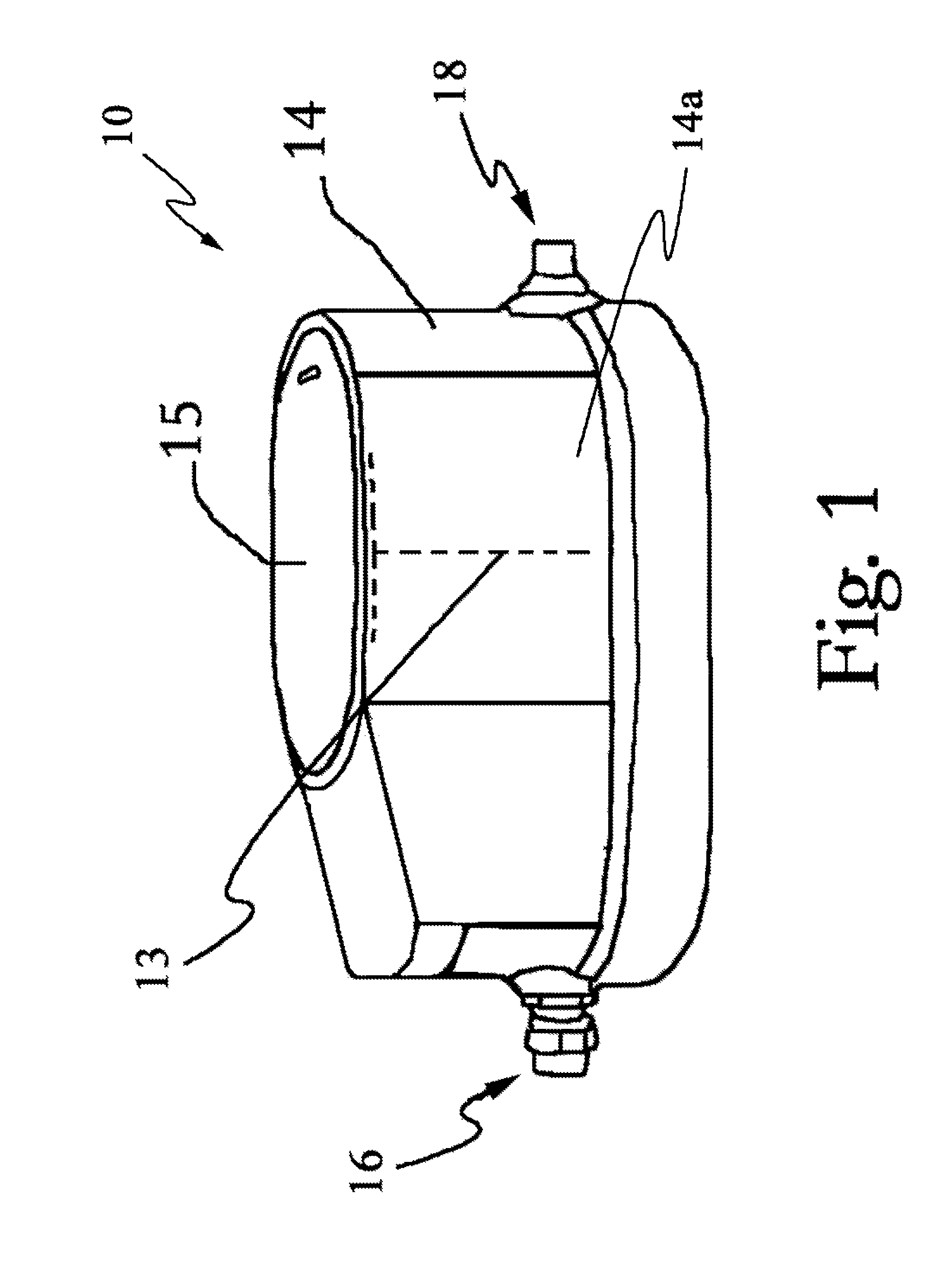
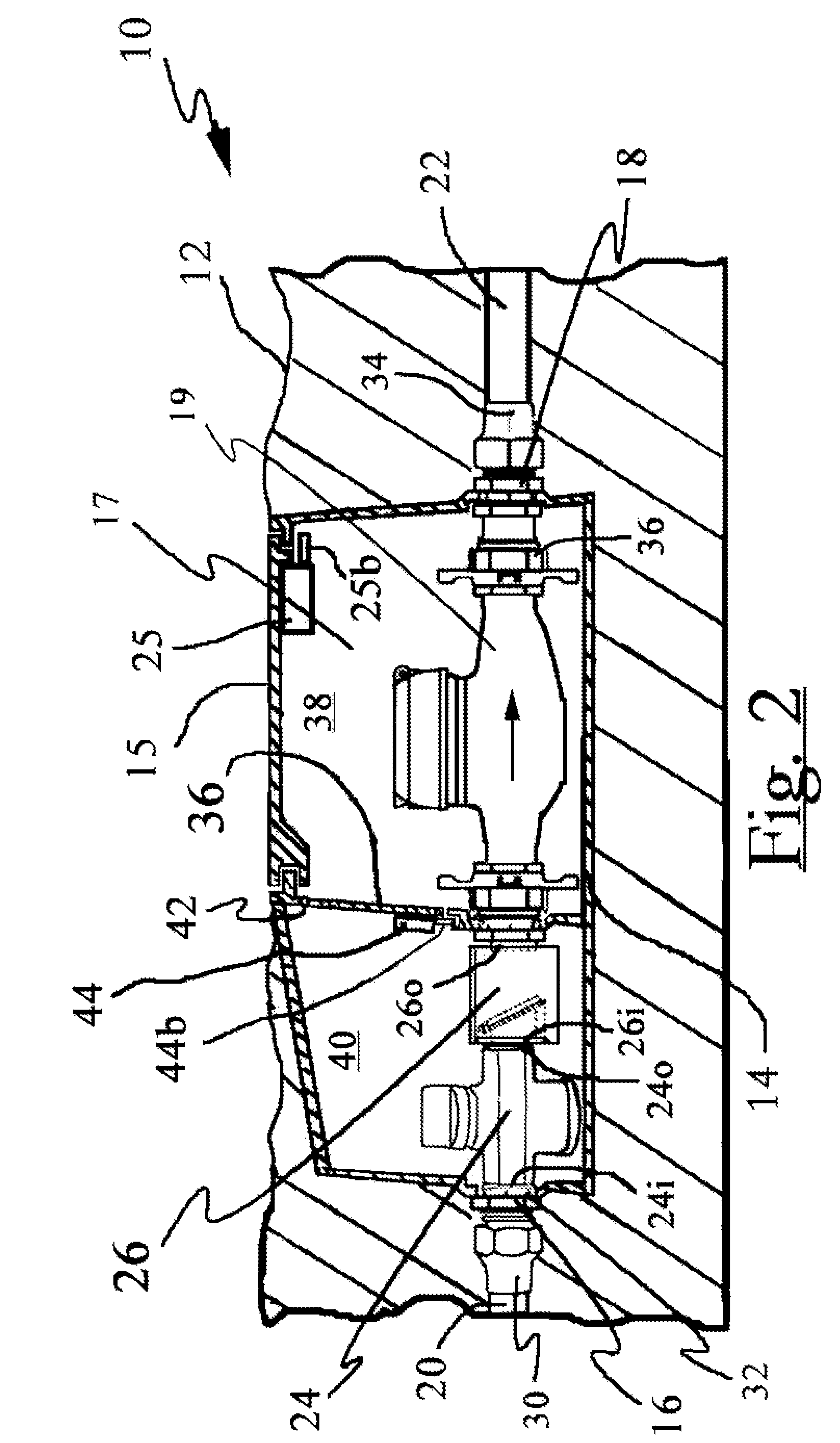
TECHNICAL FIELD OF THE INVENTION[0001]The present invention relates to smart utility meter boxes. One embodiment is configured with substantially all the necessary hardware required for receiving a utility meter and for associating a utility service line to a consumer service line. The smart utility meter box may comprise various mechanical / electronic features that are selectable as desired for a particular installation. The configurable features may include a meter setter with a bypass stabilizer line, quick disconnects, EM energy converter, transmitter, receiver, remote electronic module, power source, electronic shutoff, tamper detection sensors, resources attribute sensors, environmental monitoring sensors, flow monitoring sensors, and data storage features.BACKGROUND OF THE INVENTION[0002]Containers for housing utility meters that meter the consumption of a resource such as gas, electricity, or water have been in use for years. One general container of interest is a water meter...

Claims


Application Information

Patent Timeline
Patent Type & Authority Patents(United States)
IPC IPC(8): G01F15/06
CPCG01D4/002G01D11/245G01F1/075G01F15/005G01F15/063G01F15/14G01F15/18G01F15/185G07F15/10Y02B90/241Y04S20/32Y02B90/20Y04S20/30Y10T137/86501
Inventor PARRIS, EARL H.KAY, JOHN MICHAEL
Owner PARRIS EARL H
Why Eureka
Try Eureka