Wave receiving device and method of determining wave reception

a wave receiving and wave technology, applied in the field of wave receiving, can solve the problems of inability to accurately determine the timing the ultrasonic signal reception device suffers, and the ultrasonic signal reception may possibly be determined in error, so as to achieve accurate determination of ultrasonic signal reception timing

Inactive Publication Date: 2011-02-01
NEC DISPLAY SOLUTIONS LTD
View PDF16 Cites 46 Cited by
  • Summary
  • Abstract
  • Description
  • Claims
  • Application Information

AI Technical Summary

Benefits of technology

[0012]It is an object of the present invention to provide a wave receiving apparatus and a method of determining the reception of a wave signal for accurately determining ultrasonic signal reception timing.
[0015]According to the present invention, because ultrasonic signal reception timing is not determined in error because of noise, ultrasonic signal reception timing can be determined accurately, and the ultrasonic receiving device is prevented from operating erroneously.

Problems solved by technology

Therefore, the ultrasonic receiving device suffers the following problems:
When the amplitude of the received ultrasonic signal is normal as shown at (a) in FIG. 1, since the level of noise N (disturbance noise) is smaller than a threshold value T, the ultrasonic signal reception timing can be determined by comparing the amplitude of a first wave with the threshold value T. However, when amplitude of the received ultrasonic signal is not normal as shown at (b) in FIG. 1, since the level of noise N is substantially the same as the threshold value T, the ultrasonic signal reception timing may possibly be determined in error due to the noise N.
Consequently, the ultrasonic receiver tends to detect sporadic noise or a wide range of noise, e.g., voice, the sound of a closing door, or noise generated when a display monitor is turned on, etc.
If any of these noises is contained in the received ultrasonic signal, then the ultrasonic signal reception timing may possibly be determined in error.
As described above, the conventional ultrasonic receiving devices are problematic in that they may possibly determine the ultrasonic signal reception timing in error and may possibly operate erroneously due to noise.

Method used


Image

  • Wave receiving device and method of determining wave reception
  • Wave receiving device and method of determining wave reception
  • Wave receiving device and method of determining wave reception

Examples


1st embodiment

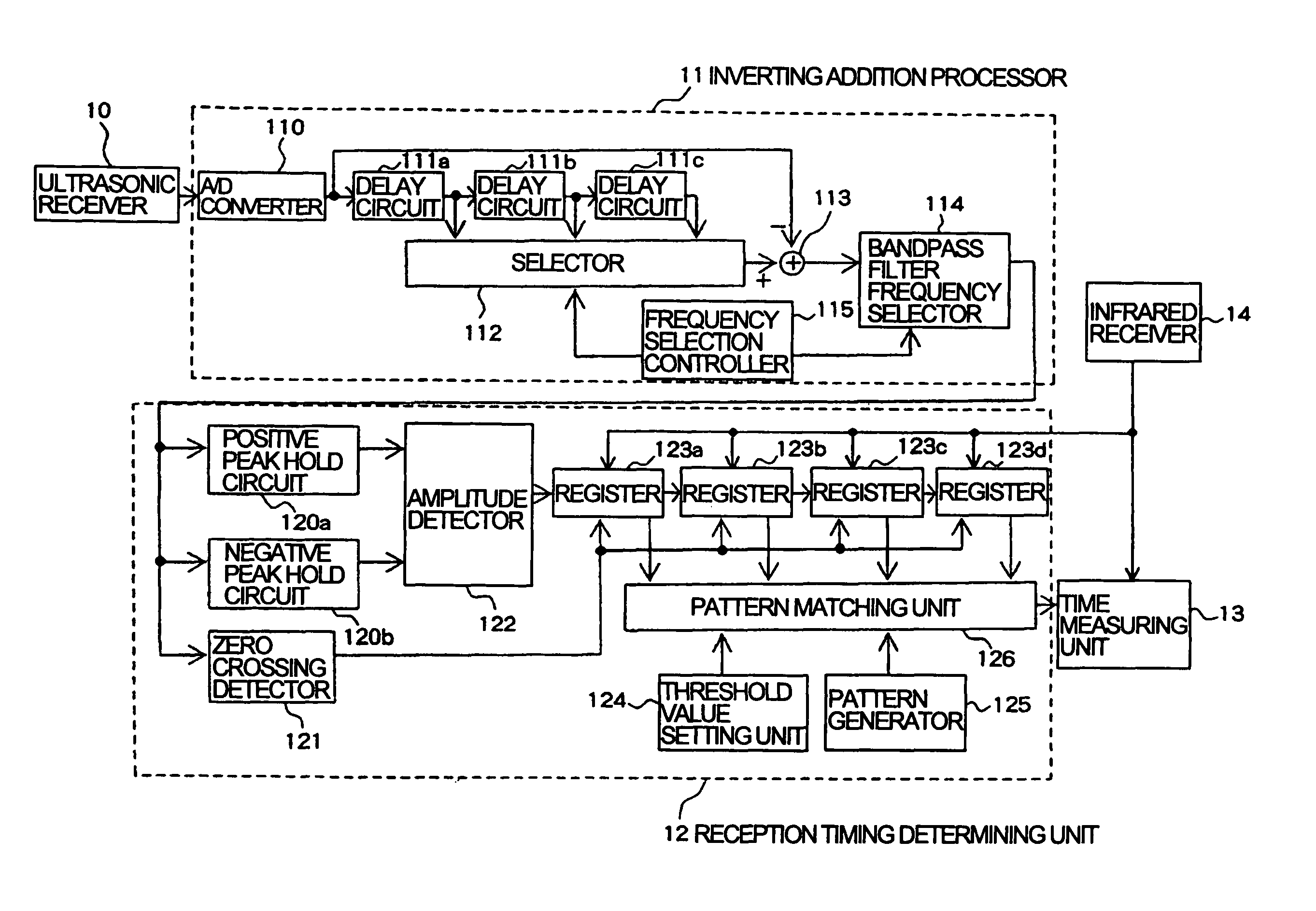
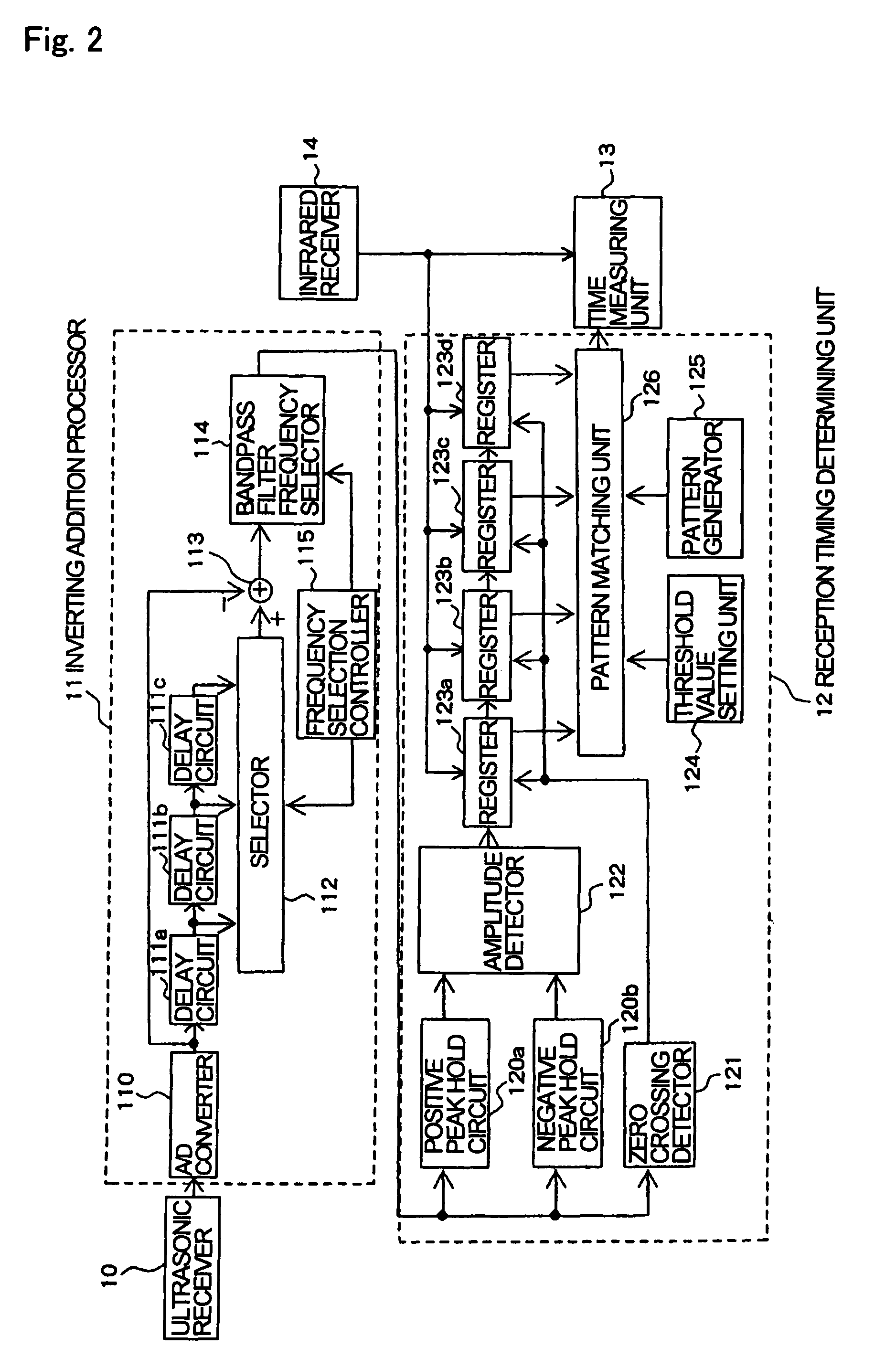
[0030]FIG. 2 shows in block form an ultrasonic receiving device according to a first embodiment of the present invention. The ultrasonic receiving device is adapted to be used in a distance measuring system for measuring the distance up to an object using an ultrasonic signal. The ultrasonic receiving device basically comprises ultrasonic receiver 10, inverting addition processor 11, reception timing determining unit 12, time measuring unit 13, and infrared receiver 14.

[0031]Ultrasonic receiver 10 serves to receive an ultrasonic signal that is transmitted in cyclic periods from a transmitting device (not shown), which is to be measured. Ultrasonic receiver 10 supplies an output signal to inverting addition processor 11.

[0032]The transmitting device also transmits an infrared signal (pulse signal) in cyclic periods. The cyclic periods of the ultrasonic signal are determined based on the cyclic periods of the infrared signal. The infrared signal transmitted from the transmitting devic...

2nd embodiment

[0098]In the ultrasonic receiving device according to the first embodiment, the received signal level in the ultrasonic receiver changes depending on the distance from itself to the transmitting device. If the transmitting device is in the form of a rod with an ultrasonic transmitter on its tip end, then the transmitting device has an ultrasonic signal radiating pattern which is lower in level at a rear end thereof. In this case, the received signal level in the ultrasonic receiver varies depending on the orientation of the transmitting device with respect to the ultrasonic receiver. Changes in the received signal level based on the distance and the orientation are liable to lower the accuracy of ultrasonic signal reception timing determined by pattern matching unit 126 in the ultrasonic receiving device according to the first embodiment which employs a fixed value as the threshold value. An ultrasonic receiving device according to a second embodiment employs a threshold value that ...


PUM


Abstract

An ultrasonic receiver receives an ultrasonic signal having a period in which an amplitude thereof progressively increases as time elapses. A pattern matching unit determines whether a comparative pattern, which is generated as a result of comparison between the respective maximum amplitude values of a plurality of successive waves of said wave signal and a threshold value set by a threshold setting unit, matches a reference pattern or not during the period of the ultrasonic signal. The pattern matching unit determines that the ultrasonic receiver has successfully received the ultrasonic signal if the comparative pattern matches the reference pattern.

Description

BACKGROUND OF THE INVENTION[0001](1) Field of the Invention[0002]The present invention relates to a wave receiving device for use in a system for measuring a distance up to an object using a wave signal represented by a sound signal including an ultrasonic signal, and a method of determining the reception of a wave signal, which is to be performed in such a wave receiving device.[0003](2) Description of the Related Art[0004]There have been presented various presentation systems utilizing projectors. One of the known presentation systems is an electronic presentation system for enabling the user to write information such as characters on an image projected by the projector, using a pointing device such as an electronic pen or the like. The electronic presentation system detects the position of the pointing device on the projected image according to an ultrasonic distance measurement process.[0005]JP-A 2001-125741 discloses a presentation system wherein a pointing rod as a pointing de...

Claims


Application Information

Patent Timeline
Patent Type & Authority Patents(United States)
IPC IPC(8): G09G5/08
CPCG01S11/16
Inventor SUZUKI, KENJIKOBAYASHI, HIROYUKIMURAYAMA, SYUUJIINAMOTO, KENJI
Owner NEC DISPLAY SOLUTIONS LTD
Why Eureka
Try Eureka