Image coding apparatus and image coding method

a technology of image coding and coding apparatus, which is applied in the field of moving picture coding technique, can solve the problems of large volume of operations, insufficient improvement in coding processing speed, and insufficient reduction of operation amount, so as to achieve the effect of reducing the amount of operations and improving processing speed

Inactive Publication Date: 2011-02-01
GK BRIDGE 1
View PDF6 Cites 31 Cited by
  • Summary
  • Abstract
  • Description
  • Claims
  • Application Information

AI Technical Summary

Benefits of technology

[0009]In view of the aforementioned problem, an object of the present invention is to provide an image coding apparatus and an image coding method which realize a reduction of the amount of the operations in selecting the intra-frame prediction mode, so that the improvement in the processing speed is realized.

Problems solved by technology

However it is necessary to calculate the prediction errors for the respective nine kinds of intra-frame modes and then compare the calculated prediction errors in order to select an optimum intra-frame prediction mode, and therefore a large volume of operations is needed.
As a result, the improvement in the speed in coding processing has not been easy. FIG. 3 is a drawing showing a coding sequence of a block by a conventional technique so as to realize the improvement in the processing speed by means of pipeline processing of the intra-frame prediction of 4×4 block.
However the amount of operations is not substantially reduced by this conventional technique, and there exists a problem that the processing speed can not be improved in a device and software in which pipelining is not able to be executed.

Method used


Image

  • Image coding apparatus and image coding method
  • Image coding apparatus and image coding method
  • Image coding apparatus and image coding method

Examples


first embodiment

[0038]Hereafter a first embodiment of the present invention will be described referring to the respective drawings.

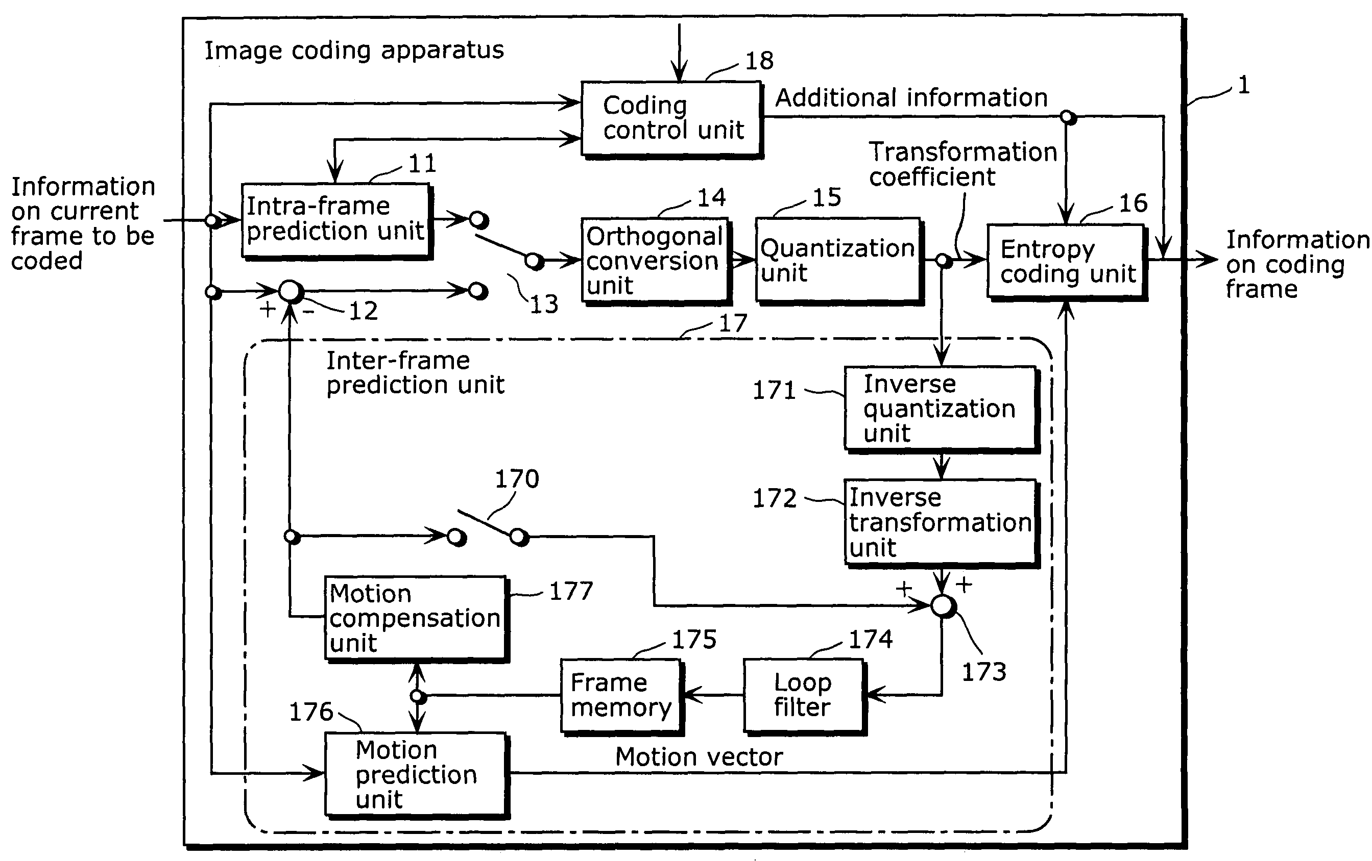
[0039]FIG. 4 is the block diagram showing the whole configuration of an image coding apparatus 1 of the present invention. The image coding apparatus 1 is an apparatus for executing the intra-frame prediction of the present invention, and the image coding apparatus 1 includes an intra-frame prediction unit 11, a difference calculation unit 12, a switch 13, an orthogonal transformation unit 14, a quantization unit 15, an entropy coding unit 16, an inter-frame prediction unit 17 for executing inter-frame prediction, and a coding control unit 18. The inter-frame prediction unit 17 has a switch 170, an inverse quantization unit 171, an inverse transformation unit 172, an adder 173, a loop filter 174, a frame memory 175, a motion prediction unit 176 and a motion compensation unit 177.

[0040]When inter-frame prediction is executed, the information on the current frame to be co...

second embodiment

[0079]Hereafter a second embodiment of the present invention will be described referring to the respective drawings.

[0080]The whole configuration of image coding apparatus 1 of the second embodiment is the same as the first embodiment shown in FIG. 4, and therefore the description is not included here.

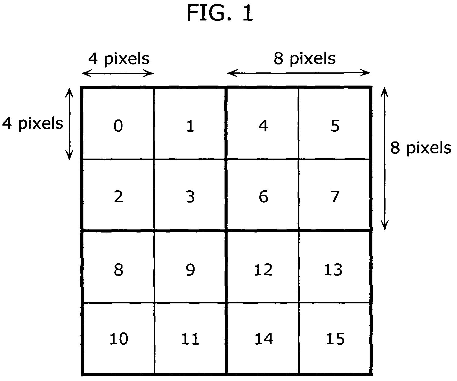
[0081]FIG. 16 is a block diagram showing the configuration of the intra-frame prediction unit 11 for the second embodiment of the present invention. The intra-frame prediction unit 11 calculates the prediction errors of the 8×8 block in the 16×16 macro block by skipping some pixels, and determines the intra-frame prediction mode of the 4×4 block in the 8×8 block. The intra-frame prediction unit 11 includes a pixel selection unit 61, a mode error value calculation unit 42, an inter-mode comparison unit 43, and a block prediction value calculation unit 62.

[0082]Here the prediction error calculation unit corresponds to the block prediction value calculation unit 62, the macro block mode d...


PUM


Abstract

An image coding apparatus executes intra-frame prediction with a predetermined intra-frame prediction mode for a certain block. A block selection unit judges that the current block to be coded is a prediction error calculation block or a non-prediction error calculation block. In the case where the current block is a prediction error calculation block, a mode error value calculation unit calculates the prediction error by the sum of absolute differences and for all of the intra-frame prediction modes, an inter-mode comparison unit compares the prediction errors, and as a result of the comparison, an intra-frame prediction mode having the minimum prediction errors is determined as the intra-frame prediction mode. In the case where the current block is a non-prediction error calculation block, the prediction error is not calculated. As an alternative, a prediction mode estimation unit determines the intra-frame prediction mode based on the neighboring prediction mode information stored in a storage unit.

Description

BACKGROUND OF THE INVENTION[0001](1) Field of the Invention[0002]The present invention relates to a coding technique for a moving picture. The present invention relates, in particular, to a technique for reducing the amount of operations required for coding the moving picture by a technique that efficiently selects one intra-frame prediction mode out of plural kinds of intra-frame prediction modes in coding the moving picture by the H.264 standard.[0003](2) Description of the Related Art[0004]In recent years, digitalization of AV information has made great progress, and devices which are capable of handling a digitalized video signal have become popular. Incidentally, the video signal contains a large volume of information, and it is therefore more desirable to code the video signal by reducing the amount of information considering storage volume and transmission efficiency. The international standard H.264 is standardized as an image signal coding technique. In the H.264 standard, ...

Claims


Application Information

Patent Timeline
Patent Type & Authority Patents(United States)
IPC IPC(8): H04N7/12H04N19/50H03M7/36H04N19/107H04N19/11H04N19/134H04N19/137H04N19/156H04N19/176H04N19/196H04N19/593H04N19/60H04N19/61H04N19/91
CPCH04N19/159H04N19/176H04N19/61H04N19/137H04N19/11H04N19/14H04N19/593
Inventor ARIMURA, KOJIARAKAWA, HIROSHITASAKA, KEIMASUNO, TAKASHI
Owner GK BRIDGE 1
Why Eureka
Try Eureka