Image data compression method and image data compression device

a compression method and image technology, applied in the direction of geometric image transformation, visual presentation, instruments, etc., can solve the problems of increased cost, data quantity may exceed the memory capacity, printing cannot be performed, etc., and achieve the effect of high speed and free space secured in the memory area

Inactive Publication Date: 2011-02-01
KONICA MINOLTA BUSINESS TECH INC
View PDF21 Cites 5 Cited by
  • Summary
  • Abstract
  • Description
  • Claims
  • Application Information

AI Technical Summary

Benefits of technology

[0019]An object of the present invention is to provide a compression method for compressing image data to have data quantity less than predetermined target data quantity, in which more free space in a memory area can be secured than the conventional method, and high speed process can be realized while controlling deterioration of image quality below a minimum level.
[0022]According to a third aspect of the present invention, the step of generating the modeled data may include a step of generating a representative value of the image data of each of the regions, and a step of generating an indicator that indicates whether or not a pseudo gradation image dot pattern that is a dot pattern indicated by the pseudo gradation image data can be reproduced correctly when the dot pattern of the region is reproduced based on the representative value.
[0032]According to the present invention, in the compression process for compressing image data to be within a predetermined target data quantity, more free space can be secured in a memory area than the conventional method, so that the process can be performed at high speed while controlling deterioration of image quality below a minimum level.

Problems solved by technology

This will cause an increase in cost.
Therefore, if the memory capacity of the printing apparatus is reduced based on expectation that the data quantity after the compression becomes small, the data quantity may exceed the memory capacity.
If the data quantity exceeds the memory capacity, the printing cannot be performed.
Then, however, the memory capacity cannot be reduced after all.
Therefore, data quantity after the compression becomes much smaller than the memory capacity in most cases, so there will be excessive memory area as waste.
In this printing apparatus, the above-mentioned excessive memory area as waste will further increase.
Usually, image data has large data quantity, so keeping the image data can be a large load on an apparatus that performs compression.
If the memory is occupied, other processes of the apparatus may be troubled.
In the case where the image data is reread when the compression process is performed, the entire process may be largely delayed because the reading process may take a long time.
On the contrary, if the compression process is started with setting of a compression parameter that causes a lot of loss of information quantity in the compression process, i.e., a compression parameter having a high compression ratio, a lot of information may be discarded needlessly so that unnecessary deterioration in image quality may be caused.
Therefore, it is difficult to achieve both optimization of image quality and an increase of process speed.

Method used


Image

  • Image data compression method and image data compression device
  • Image data compression method and image data compression device
  • Image data compression method and image data compression device

Examples


first example

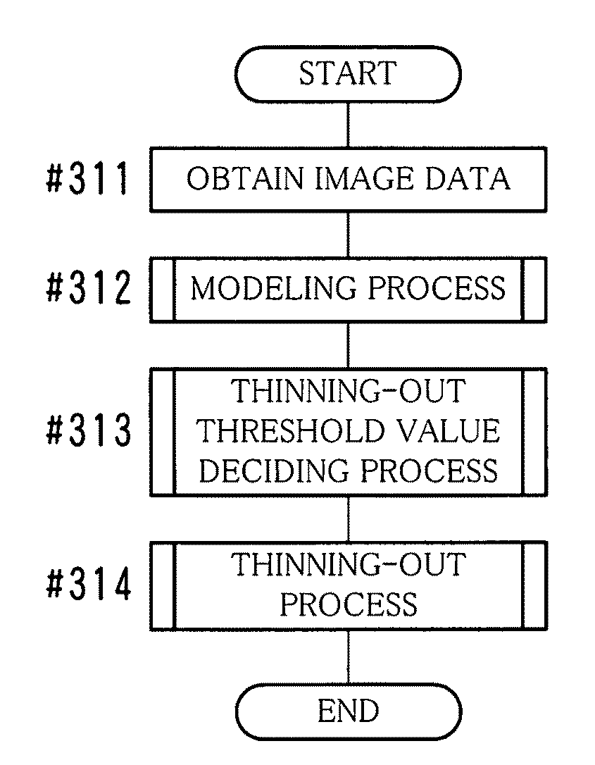
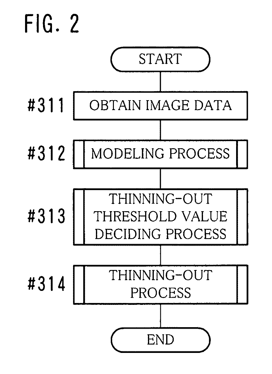
[0095]In the present example, a representative value is decided for each of the divided regions TL of the pseudo gradation image data D1, and the representative value is used for generating the compressed image data AD. The representative value as to the divided region TL is a value that represents density values in the divided region TL directly or indirectly. By using the representative value and the dither pattern DP, it is possible to reproduce the original pseudo gradation image or an image that is similar to the same. Hereinafter, the process of the present example will be described by dividing it into items including a “modeling process”, a “thinning-out process”, a “coding process”, a “thinning-out threshold value deciding process” and the like.

[Modeling Process]

[0096]When the modeling process is performed, a representative value of each of the divided regions TL is decided first. Here, the number of dots included in the divided region TL is used as the representative value ...

second example

[0195]In the present example, the case where the compressed image data AD is generated by performing orthogonal transformation on the density value of the image data FD having gradation with respect to each divided region TL will be described. As the orthogonal transformation, discrete cosine transformation (DCT), wavelet transformation or the like can be used. In the present example, the case where the discrete cosine transformation is performed will be described.

[Modeling Process]

[0196]FIG. 18 shows density values of the pixels TP of the divided region TL in the image data FD having 256 levels of gradation. In the modeling process of the present example, each of density values of pixels is shifted in level to the negative side by 128 bits. In other words, “128” is subtracted from the density value of each of the pixels. Thus, the density values are converted into the values shown in FIG. 19.

[0197]Next, the discrete cosine transformation is performed on each of the density values a...

third example

THE THIRD EXAMPLE

[0241]In the present example, the case where the compressed image data AD is generated by performing the Block Truncation Coding (BTC) process on each divided region TL of the image data FD having gradation will be described.

[Modeling Process]

[0242]FIG. 27A shows a gradation image of the divided region TL. First in the modeling process, a region average that is an average of density values of the divided region TL is determined. Pixels having density values that are thicker than the determined region average (high density pixels) are discriminated from pixels having density values that are thinner that the same (low density pixels), and a first average that is an average of density values of thick pixels and a second average that is an average of density values of thin pixels are determined (see FIG. 27B). Furthermore, as shown in FIG. 27C, a virtual dot pattern that is a dot pattern in the case where pixels having density values thicker than the region average are ...


PUM


Abstract

An image data compression method includes the steps of dividing image data into predetermined regions, generating modeled data by extracting a feature of the image data for each of the regions, performing trial calculation of data quantity of compressed data that is generated by a thinning-out process in which data is thinned out from the modeled data based on a threshold value concerning the thinning-out process, determining a thinning-out threshold value that is a threshold value such that the data quantity becomes equal to or less than a predetermined target data quantity, and performing the thinning-out process based on the thinning-out threshold value so that compressed data is generated.

Description

[0001]This application is based on Japanese patent application Nos. 2006-106864 and 2007-031892 filed on Apr. 7, 2006 and Feb. 13, 2007, respectively, the contents of which are hereby incorporated by reference.BACKGROUND OF THE INVENTION[0002]1. Field of the Invention[0003]The present invention relates to an image data compression method and an image data compression device.[0004]2. Description of the Prior Art[0005]In general, a printing apparatus such as a printer or multi-function peripherals (MFP) is equipped with a memory for storing image data to be printed. The printing apparatus starts printing job after the image data that is generated by a personal computer or the like is stored in the memory for usually at least one page (corresponding to approximately 100 megabytes in an uncompressed state).[0006]In consideration of recent requirement for high image quality, data size (data quantity) of an image that is used for printing has a tendency of increasing enormously. If the im...

Claims


Application Information

Patent Timeline
Patent Type & Authority Patents(United States)
IPC IPC(8): G06K9/36G06K9/46G06K15/00H04N1/405G06T3/40H04N1/41H04N19/132H04N19/136H04N19/146H04N19/167H04N19/196H04N19/426H04N19/59H04N19/60H04N19/625H04N19/91
CPCH04N19/176H04N19/46H04N19/13H04N19/149H04N19/15H04N19/90H04N19/124H04N19/132H04N19/182H04N19/192H04N19/60
Inventor YAMAMOTO, TOSHITSUGU
Owner KONICA MINOLTA BUSINESS TECH INC
Why Eureka
Try Eureka