
Communications line monitoring system, relay apparatus, and communications line monitoring method

a communication line and relay technology, applied in the field of monitoring the quality of communications lines, can solve the problems of insufficient process performance, drastic increase in the number of processes, and adverse effects

Inactive Publication Date: 2011-02-01
FUJITSU LTD
View PDF7 Cites 8 Cited by
  • Summary
  • Abstract
  • Description
  • Claims
  • Application Information

AI Technical Summary

Problems solved by technology

Meanwhile, the smallest unit of a path is required to remain the same as the existing lines from the market since there is a problem regarding removing the existing lines.
This means the increase in the number of paths per one relay apparatus monitored by a communications line monitoring apparatus results in an adverse effect such as a drastic increase in the number of processes of a communications line monitoring apparatus performing central management of each relay apparatus in the network.
However, even if the priority control is performed, there may be a case that the processes are not performed sufficiently such as a case of communications line failure such that a large quantity of notification messages is transmitted from relay apparatuses.
Consequently, congestion may be caused in the transmission paths (control lines) of notification messages, or loading of processes in the communications line monitoring apparatus may increase drastically.
Because this would cause delay in execution of highly prioritized processes, it is considered as problem.

Method used


Image

  • Communications line monitoring system, relay apparatus, and communications line monitoring method
  • Communications line monitoring system, relay apparatus, and communications line monitoring method
  • Communications line monitoring system, relay apparatus, and communications line monitoring method

Examples


embodiment 1

Variation of Embodiment 1

[0113]In the embodiment 1, two (an even number) of user areas are used as the storage area of the “previous error detection determination information” such as the “previous error detection information” and the “error undetected information”. In this variation, however, a single (an odd number) user area alone is used as a storage area of the “previous error detection determination information”.

[0114]In order to realize such a form, a configuration such that the single user area is removed from the operation range of the parity operation implemented in each node is required, given that, the expected value is to be used in the parity operation of the single user area without changing the parity operation range.

[0115]In this embodiment, first, calculation of BIP-8 is performed to all bits of the path frame P, shown in a shaded area in FIG. 3, in a device generating path frames. The calculation result (ire. BIP-8 code) is stored in the B3 area of the frames tran...

embodiment 2

[0130]This example uses an upper apparatuses' configuration for monitoring line quality information in an apparatus in which section termination is not performed.

[0131]In the embodiment 2, a configuration of the transmission device between nodes in the above network is presented as an example.

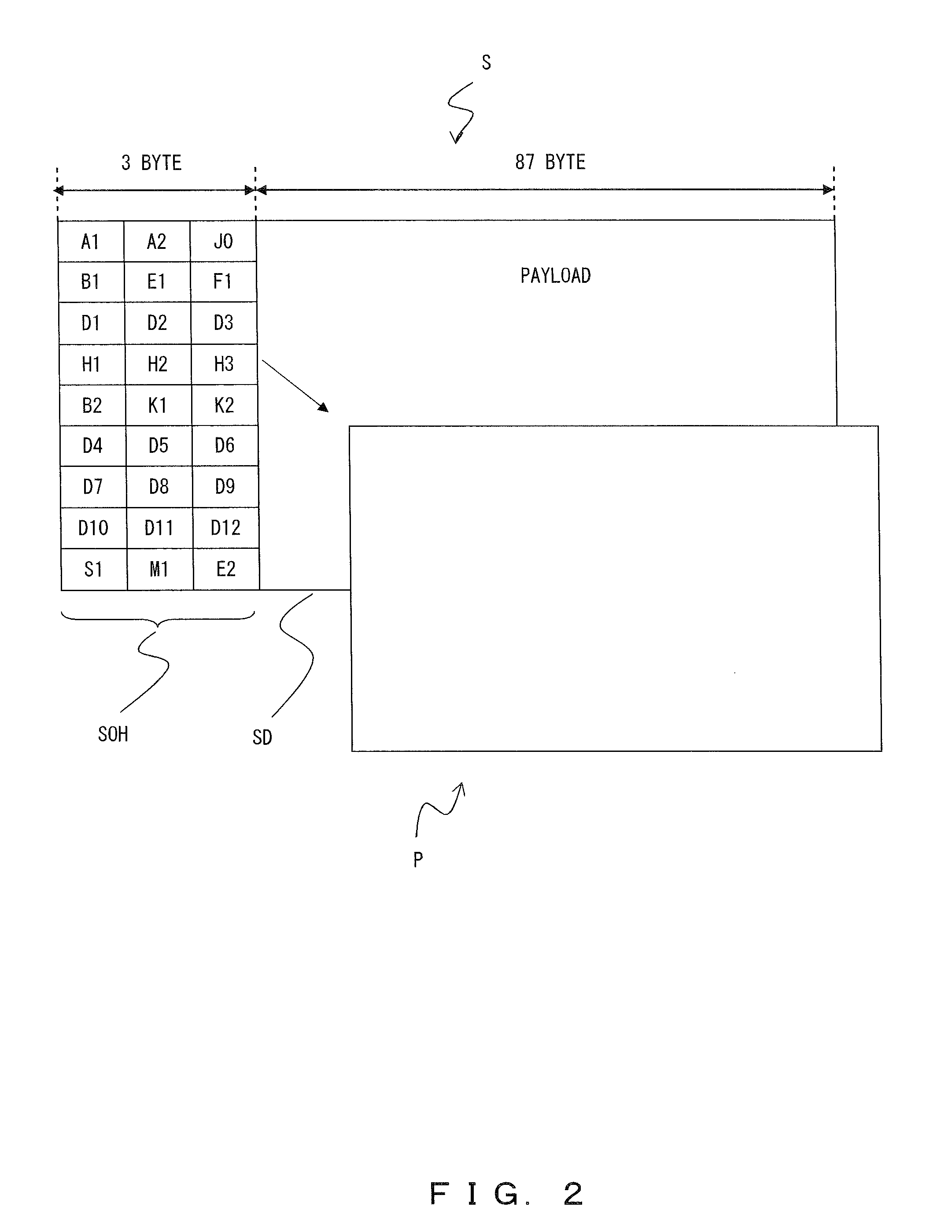
[0132]As a premise in this example, information in the B1 byte and the B2 byte provided in the overhead unit SOH of the section frame is to be the check target of the line quality. In other words, by comparing the information stored in the B1 byte and the B2 byte with the parity operation result in the receiver apparatus, the line quality is checked.

[0133]In addition, as a storage area of the previously detected information for the B1 byte (or the B2 byte), an unused byte (the D4 byte in the example) of the section overhead unit SOH is used. Particularly in this example, as the storage area of the previously detected information when the B1 byte and the parity operation result are different, th...

embodiment 3

[0164]In the embodiments 1-2, a configuration in which parity operation previously detected information is transferred using the same line as the data transfer is shown. However, in the present embodiment, the configuration is one in which the parity operation previously detected information is transferred using a separate line.

[0165]As an example, a WDM (Wavelength Division multiplexing) apparatus, which does not perform the section termination, is explained.

[0166]In this apparatus, a signal with a plurality of wavelength channels being multiplexed is demultiplexed by wavelengths, and among the demultiplexed channels, a channel for data transfer (a main signal line) and a supervisor channel with a wavelength different from the main signal line (a sub signal line) are used. The sub-signal line is used for transferring a control signal of the WDM apparatus. Note that the sub-signal line is not an exclusive line for transmitting a notification message; however, in the examples describ...


PUM


Abstract

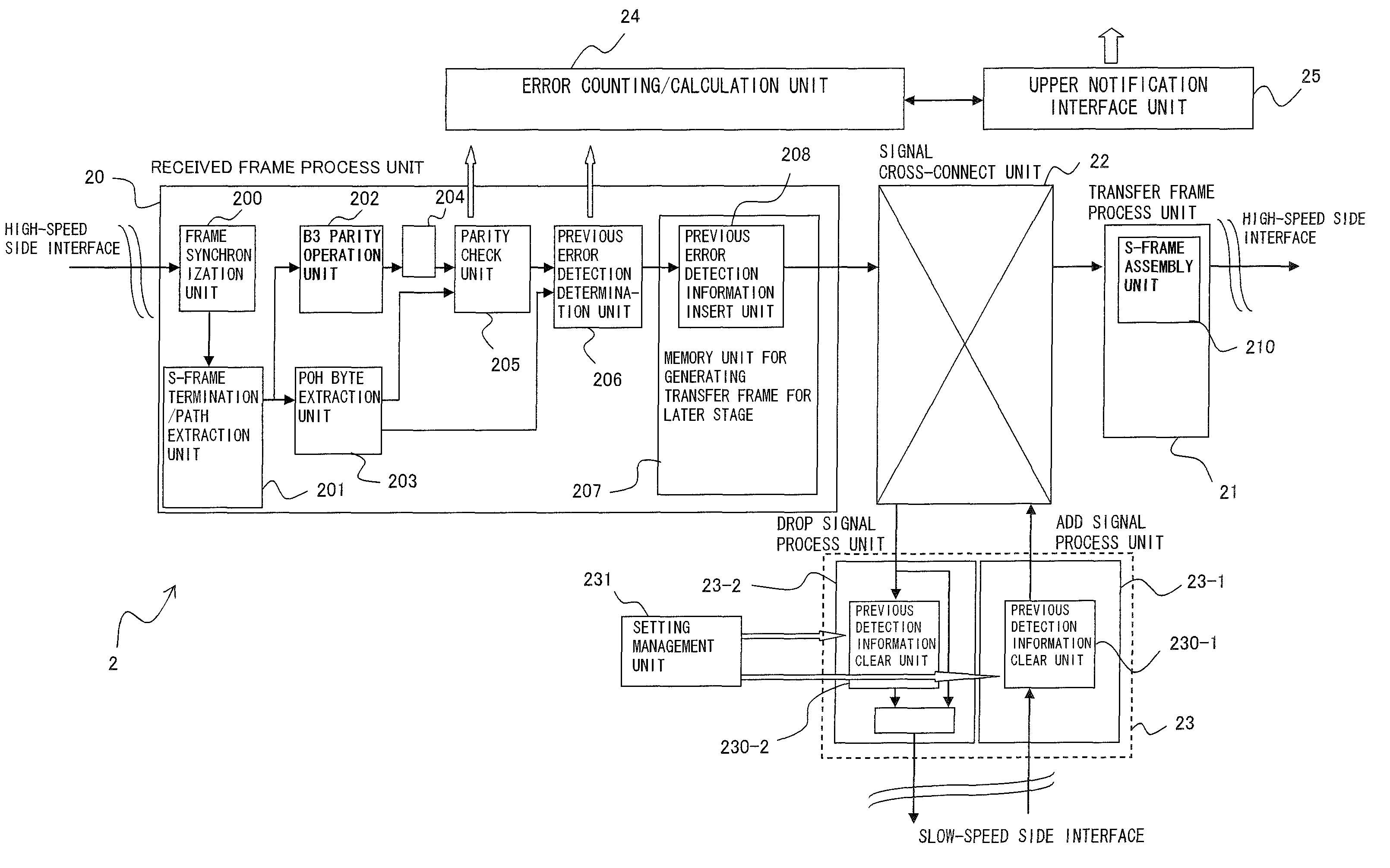
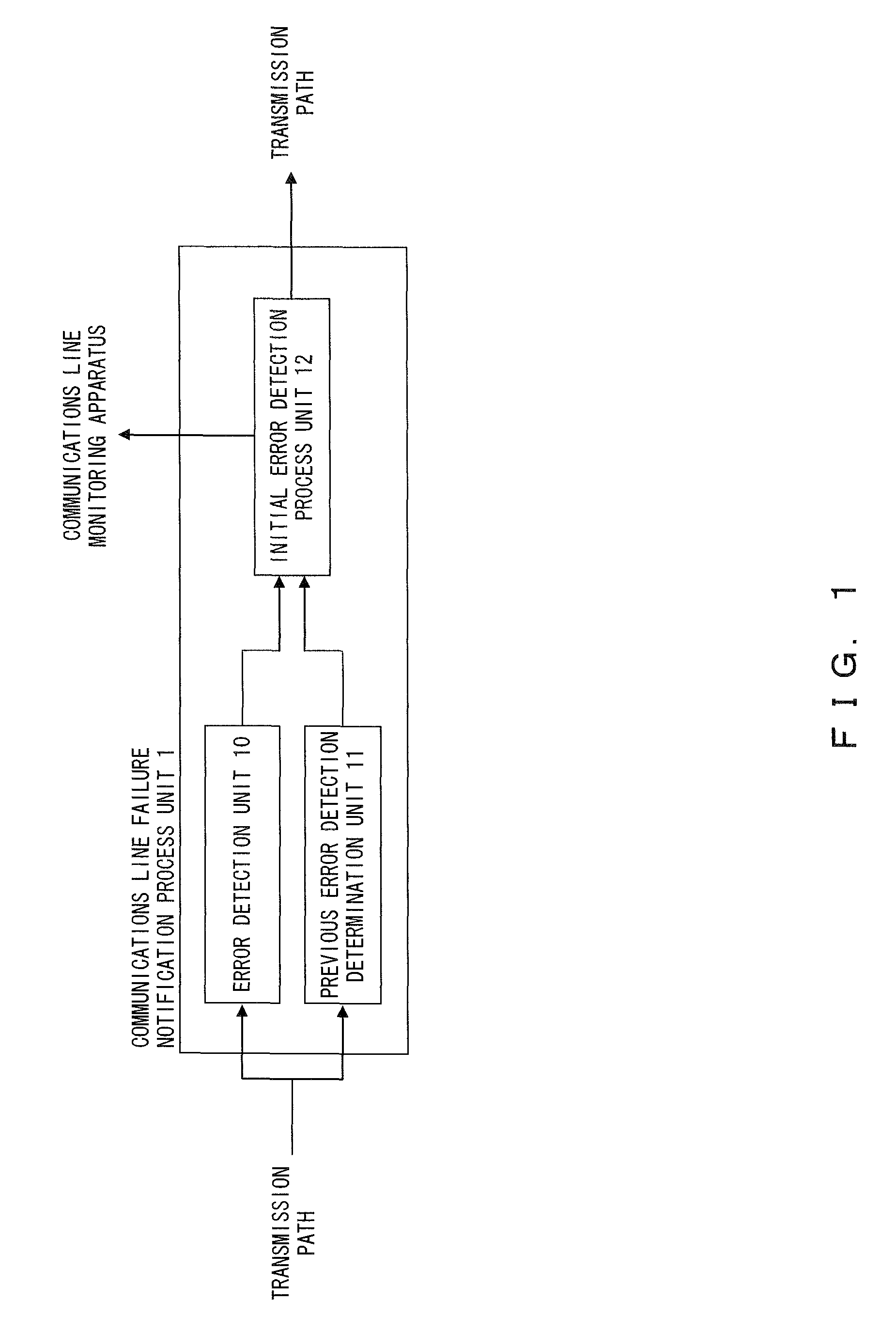
A communications line monitoring system of the present invention comprises a plurality of relay apparatus and a communications line monitoring apparatus for monitoring a line quality of a communications line of relayed data, and each of the relay apparatus comprises error detecting unit for detecting errors in received data, previous error detection determination unit for determining whether or not error detection has already been performed in other apparatus based on previous error detection information of the received data, and initial error detection process unit for, only when an error is detected and the error was undetected in other apparatus, autonomously notifying error detection information to the communications line monitoring apparatus, and for adding previous error detection information to data for transmission.

Description

BACKGROUND OF THE INVENTION[0001]1. Field of the Invention[0002]The present invention relates to a technology for monitoring the line quality of communications lines.[0003]2. Description of the Related Art[0004]Synchronous Digital Hierarchy / Synchronous Optical Network (SDH / SONET) is one of several standards of optical transmission technologies, which enable high-speed line transmissions through combining and multiplexing slower lines hierarchically in order to increase transmission speeds.[0005]In such a SDH / SONET network, remote management of the line quality of the entire network by a communications line monitoring apparatus can be realized by activating the performance monitoring function of a transmission apparatus established in a network.[0006]Transmission data, alternatively referred to as communication frames, transmitted through the SDH / SONET network, has an overhead unit to which an area for storing the parity operation result of a communication frame transmitted prior is ...

Claims


Application Information

Patent Timeline
Patent Type & Authority Patents(United States)
IPC IPC(8): H03M13/00
CPCH04J3/14H04J2203/006
Inventor TAKAKUWA, MAKOTO
Owner FUJITSU LTD
Learn More