Mechanical seal

a mechanical seal and sealing end technology, applied in the direction of engine seals, leakage prevention, machines/engines, etc., can solve the problems of o-rings not sliding smoothly following, mechanical seal failure to achieve effective sealing function, and damage to sealing end faces, etc., to achieve good sealing

Active Publication Date: 2011-02-08
NIPPON PILLAR PACKING CO LTD
View PDF15 Cites 13 Cited by
  • Summary
  • Abstract
  • Description
  • Claims
  • Application Information

AI Technical Summary

Benefits of technology

[0008]It is an object of the present invention to provide a mechanical seal that has an excellent following ness of a stationary sealing ring and performs a good sealing function without the above-mentioned problem.
[0010]As a preferred embodiment of the mechanical seal according to the present invention, the mechanical seal is the static pressure type non-contact gas seal which includes a communicating space sealed by a pair of O-rings between the seal case and the stationary sealing ring, the pair of O-rings being provided away from each other at a predetermined interval, and a seal gas ejecting passage formed as a series of passages that communicate with each other through the communicating space in the seal case and the stationary sealing ring, with being open between the sealing end faces serving as the opposite end faces of the both sealing rings, thereby so as to maintain the sealing end faces in proper non-contact state by introducing the seal gas under a predetermined pressure into the space between the sealing end faces through the seal gas ejecting passage.
[0015]According to the present invention, it is possible to provide a mechanical seal in which the O-rings smoothly slide on the seal case in accordance with the movement of a stationary sealing ring and has an excellent following ness of the stationary sealing ring. Accordingly, in a mechanical seal such as a static pressure type non-contact gas seal or the like, it is always possible to obtain excellent sealing function without the deterioration of the sealing function. A resin coating film covers a portion, with which the sealed fluid comes in contact (plus a portion with which the seal gas comes in contact in case of the static pressure type non-contact gas seal) of the seal case, as well as a portion, with which the O-rings come in contact, of the seal case. Accordingly, it is possible to prevent metal ions, which are generated by contacting the sealed fluid and / or seal gas with the seal case made of a metal, from being generated. In addition, even when it is necessary to prevent metal ions from being generated, it is possible to obtain an excellent sealing function. Moreover, a portion, with which the seal fluid comes in contact, of the case is covered with the resin coating film having high corrosion resistant or chemical resistant. Therefore, even when the sealed fluid has corrosiveness, the mechanical seal can obtain an effective sealing function without corrosion of the seal case made of a metal.

Problems solved by technology

However, the O-rings, being held engaging with the stationary sealing ring, slide in press contact with the periphery of the seal case in accordance with the movement of the stationary sealing ring in the axial direction thereof, and consequently cause the following problems.
That is, since the seal case is made of a metal having an excellent strength in view of the function, the O-rings do not slide smoothly following the movement of the stationary sealing ring owing to the high contact resistance between the O-rings and the seal case.
As a result, the stationary sealing ring, which does not move smoothly in the axial direction thereof, deteriorates its own following ness so as to result in failure of an effective sealing function by the mechanical seal.
Particularly, when the supply of the seal gas stops in the above-mentioned static pressure type non-contact gas seal, it is concerned that the stationary sealing ring, which does not smoothly move toward the rotary sealing ring, may intensively collide against the rotary sealing ring, so that the sealing end faces may be damaged by some possibility.
In this case, it is concerned that the resumed supply of the seal gas does not generate a proper static pressure between the sealing end faces but leads to the lost sealing function.
There occurs, similarly, such a problem in an end face contact type mechanical seal, in which the both sealing rings are slidably rotated relative to each other to obtain a sealing function, and also in a dynamic pressure type non-contact type mechanical seal which is configured to maintain the sealing end faces in non-contact state by dynamic pressure generated therebetween.

Method used


Image

  • Mechanical seal
  • Mechanical seal
  • Mechanical seal

Examples


Embodiment Construction

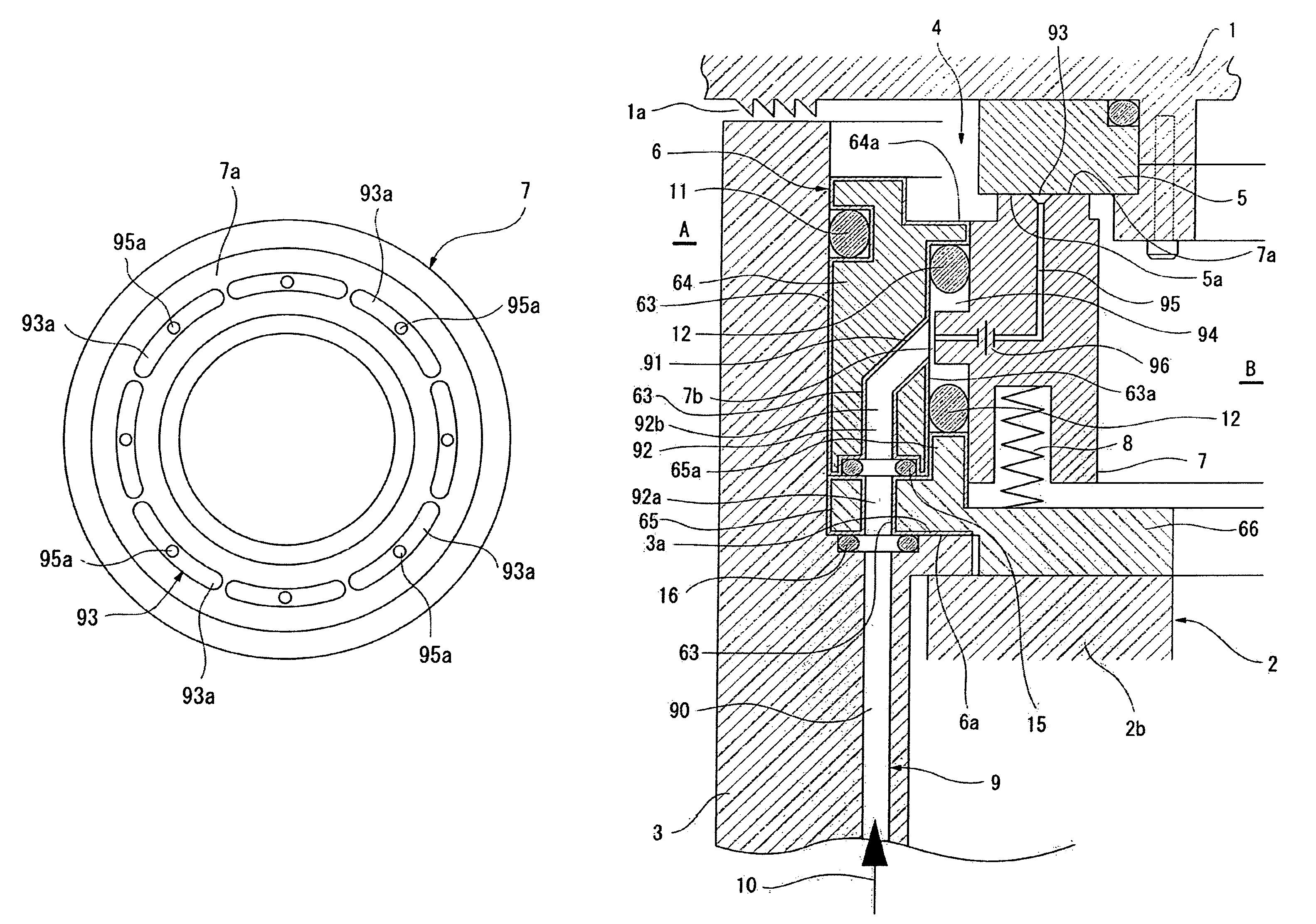
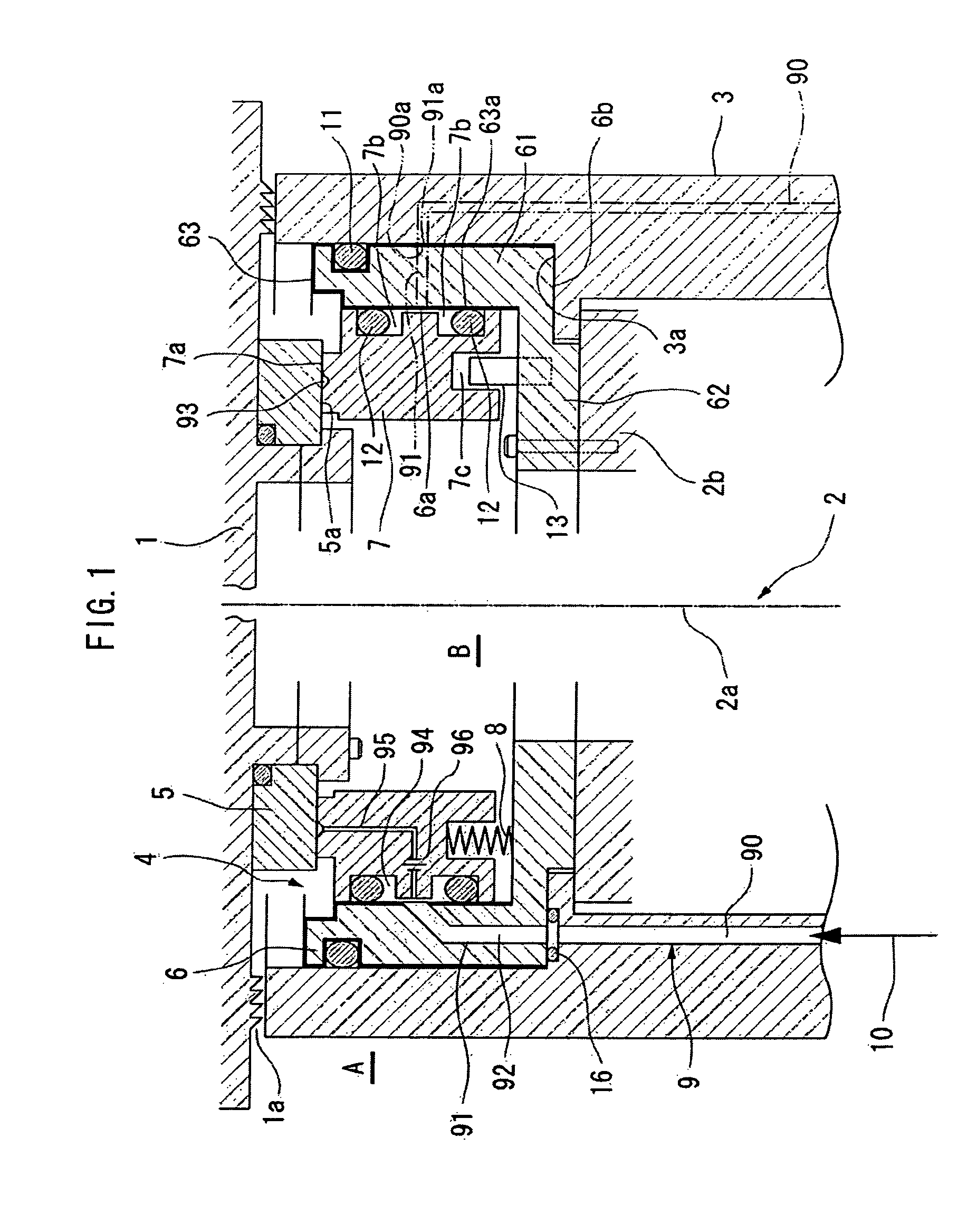
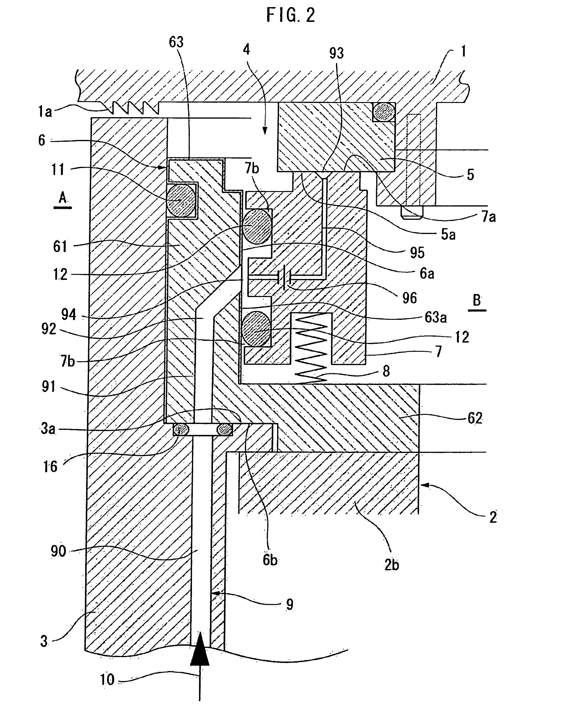
[0060]FIG. 1 is a front cross-sectional view showing an embodiment of a treatment device having a mechanical seal 4 according to the invention, and FIG. 2 is an enlarged view showing the main parts thereof. In the treatment device, a driving unit 2 of a rotary table 1 is covered with the cylindrical plastic cover 3. When appropriate treatments (cleaning treatment, chemical treatment, and the like) are performed on substrates (which are objects to be treated, such as a semiconductor wafer, a substrate of an electronic device, a liquid crystal substrate, a photomask, a glass substrate, and the like) by using the rotary table 1, a treatment area A (a fluid sealed area) and an inside area B (which is an atmosphere area, and hereinafter referred to as a ‘inside area of cover’) of a plastic cover 3 (a fluid non-sealed area) in which the rotary table 1 is disposed are screened from each other by the mechanical seal 4 so that the treatment area A is kept clean.

[0061]In addition, the driving...


PUM

PropertyMeasurementUnit
thicknessaaaaaaaaaa
thicknessaaaaaaaaaa
depthaaaaaaaaaa

Abstract

A mechanical non-contact gas seal including a rotary scaling ring and a stationary sealing ring that is engaged and held in an inner periphery of a seal case by means of O-rings so as to move in an axial direction thereof. The O-rings engage with the outer periphery of the stationary sealing ring and come in press contact with the inner periphery of the seal case to seal a gap between the stationary sealing ring and the seal case while allowing the stationary sealing ring to move in an axial direction. A resin coating of a thickness in the range of 5 to 100 μm is formed on the inner periphery of the seal case at least within a range in which the O-rings relatively move with the movement of the stationary sealing ring.

Description

TECHNICAL FIELD[0001]The present invention relates to a mechanical seal including a rotary sealing ring that is fixed to a rotating shaft, and a stationary sealing ring that is held by means of O-rings in a seal case through which the rotating shaft passes, so as to move in an axial direction thereof, the seal case being made of a metal, wherein the O-rings are held engaging with the periphery of the stationary sealing ring and come in press contact with the periphery of the seal case so as to give a secondary seal to a gap between the stationary sealing ring and the seal case, while allowing the stationary sealing ring to move in the axial direction thereof.BACKGROUND ART[0002]A static pressure type non-contact gas seal has been known as a conventional mechanical seal, including a rotary sealing ring that is fixed to a rotating shaft; a stationary sealing ring that is held by means of a pair of O-rings in a seal case through which the rotating shaft passes, so as to move in an axia...

Claims


Application Information

Patent Timeline
Patent Type & Authority Patents(United States)
IPC IPC(8): F16J15/34
CPCF16J15/342B29B7/22B29B7/58F16J15/16F16J15/54
Inventor UEDA, MAKOTOFUJIWARA, SATOSHIKUDARI, MITSURUNINOMIYA, MASANOBU
Owner NIPPON PILLAR PACKING CO LTD
Why Eureka
Try Eureka