Powder compression molding machine and apparatus for continuous production of powder compression molded item using the machine

a technology of compression molding and compression molding, which is applied in the direction of dough shaping, manufacturing tools, pharmaceutical products, etc., can solve the problems of reducing fabrication efficiency, not suitable for compressive molding, and reducing molding speed

Active Publication Date: 2011-02-08
QUALICAPS CO LTD +1
View PDF16 Cites 8 Cited by
  • Summary
  • Abstract
  • Description
  • Claims
  • Application Information

AI Technical Summary

Benefits of technology

in view of the foregoing, the present invention has been made and it is an object of the present invention to provide a powder compression molding machine that can compressively molds powder such as powder milk into a state having high porosity at a low compression force, that can achieve satisfactory fabrication efficiency without disadvantage such as crumblingness of compacts at the time of collection, and that can efficiently fabricate compacts such as solid milk having high porosity and satisfactory shape-retaining performance, and a powder compact continuous fabrication system using this machine.
As described above, the powder compression molding machine of the present invention is configured such that the plurality of lower punches of the lower punch body and the plurality of upper punches of the upper punch body are allowed to enter the plurality of through-die holes provided in the first and second molding die sections of the slide plate, thus causing the upper and lower punches to compressively mold molding powder in the through-die holes. Therefore, even when the upper and lower punches are used to compressively mold powder at a low compression force for providing compacts having high porosity, a plurality of compacts can be molded at a time. In addition, since the two molding sections, the first and second molding die sections, are provided so that the compression molding operation is performed in one of the molding die section while compact discharge operation is performed in the other of the molding die section. Thus, the powder compression molding machine of the invention can efficiently mold compacts having high porosity without a reduction in throughput.
In addition, as described above, the powder compression molding machine of the present invention configured such that the compacts retained in the through-die holes are pressed out downwardly by the discharge pins and discharged to the downside of the slide plate formed with the through-die holes. On the downside of the slide plate the compacts are received by the compact collecting means including the trays or the like. Thus, the compacts can be satisfactorily discharged and collected without application of a large load. Even compacts that are compressively molded by a low compression force and have high porosity can be discharged and collected without being damaged.
Further, unlike the system for allowing a punch to compressively molding powder speedily and continuously, such as the conventional rotary tableting machine, the powder compression molding machine of the present invention is configured to mold a plurality of compacts at a time. Therefore, if exhibiting the same throughput as the conventional rotary tableting machine, the molding machine of the invention can perform compression molding at a relatively slow speed and at a low compression force, which can provide compacts having relatively high porosity. Further, the molding machine of the invention can be set such that compression molding may be performed by operating both the upper and lower punches without reducing the throughput.
Accordingly, the powder compact continuous fabrication system can significantly efficiently and continuously fabricates compacts that are compressively molded at a low compression force and have high porosity.
The powder compression molding machine of the present invention can satisfactorily mold and collect compacts even when e.g. powder milk or the like is compressively molded into relatively large solids having high porosity at a low compression force, and additionally provide compacts that have sufficient high porosity and are dissolvable in water or the like. Further the powder compact continuous fabrication system composed of the molding machines can significantly efficiently and continuously fabricate the compacts described above.

Problems solved by technology

Thus, they are not suitable for compressively molding the solid milk mentioned above.
If the tableting machines mentioned above perform compression molding at a lower compression force, the molding speed must be reduced because compacts may be damaged at the time of being discharged and collected from the molding machine after compressively molded.
This significantly reduces fabrication efficiency.
In addition, since the tableting machines do not essentially aim to perform compression molding at such a low compression force, it is extremely difficult to adjust porosity.
That is to say, it is difficult to stably mold solid milk having a porosity of as large as 30% or more.
Thus, compacts that are molded at a low compression force so as to increase porosity are likely to disadvantageously crumble at the time of the collection.

Method used


Image

  • Powder compression molding machine and apparatus for continuous production of powder compression molded item using the machine
  • Powder compression molding machine and apparatus for continuous production of powder compression molded item using the machine
  • Powder compression molding machine and apparatus for continuous production of powder compression molded item using the machine

Examples


Embodiment Construction

The present invention is more specifically described below illustrating an embodiment.

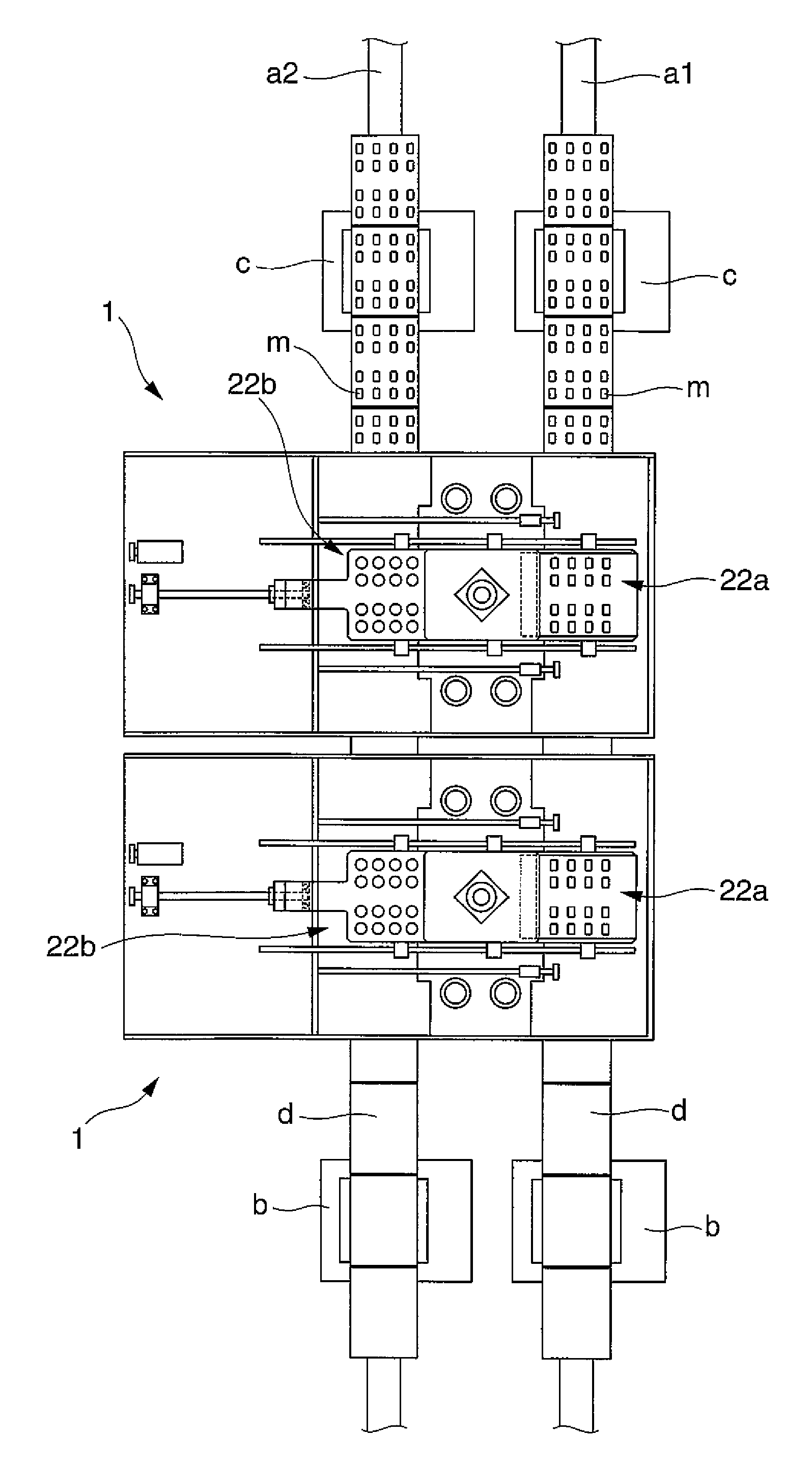
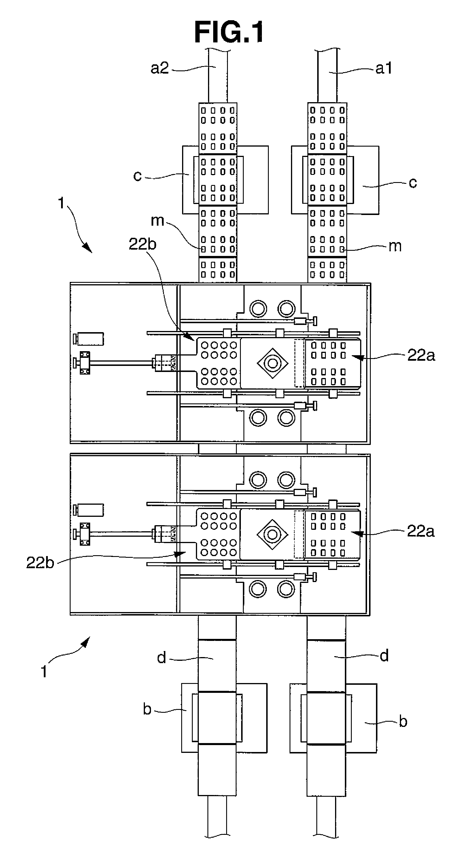
FIG. 1 illustrates a powder compact continuous fabrication system composed of powder compression molding machines 1, 1 according to the present invention. This system allows two conveyor lines including of a first conveyor a1 and a second conveyor a2 to transfer respective collection trays d for collecting compacts and allows powder compacts compressively molded by the powder compression molding machines 1, 1 to be discharge and collected on the respective collection trays d for transport.

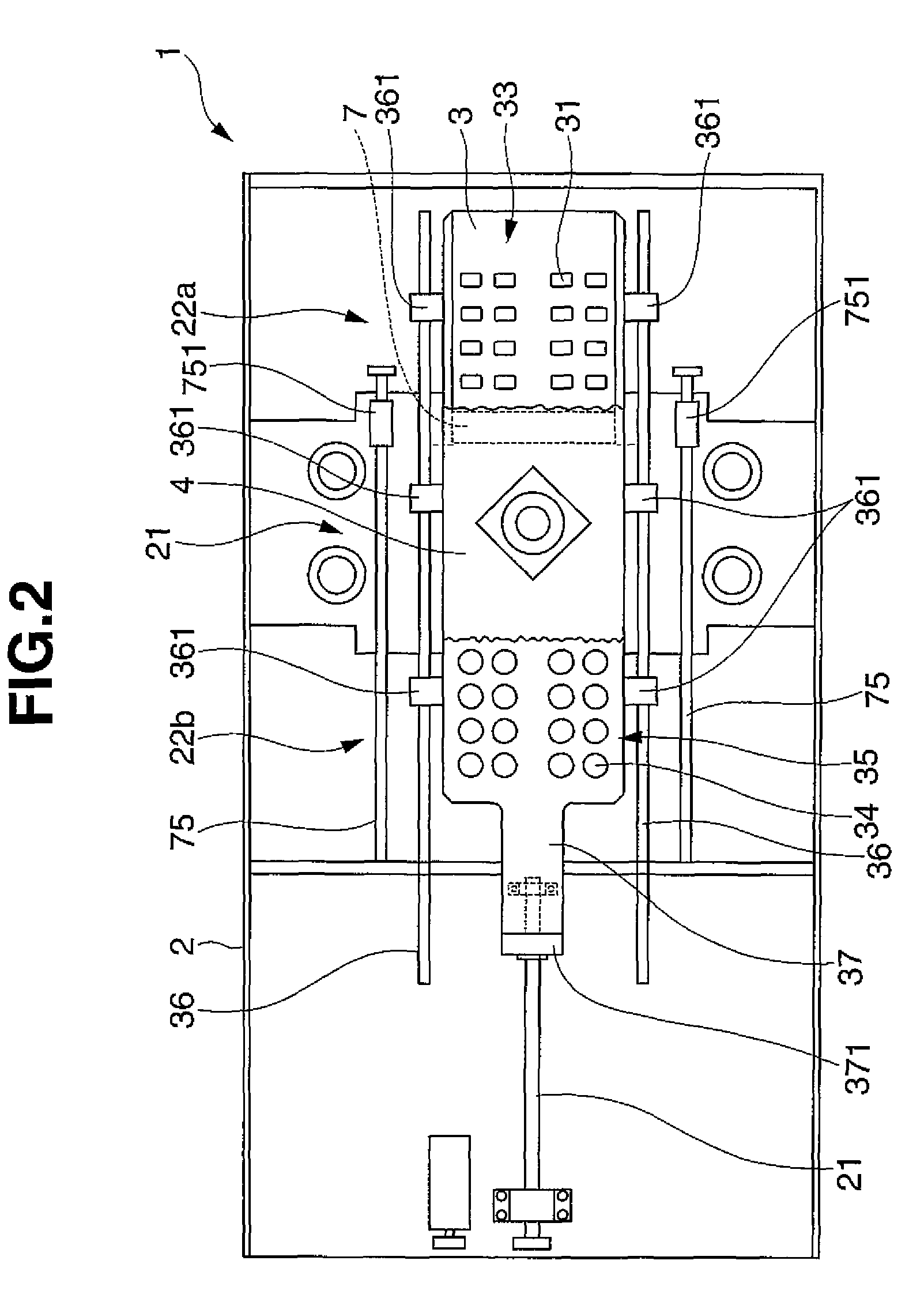
Referring to FIGS. 2 to 4, the powder compression molding machine 1 includes a machine main body 2, a slide plate 3, an upper punch body 4, compact dischargers 5a, 5b, and a lower punch 6. The machine main body 2 has a compression molding zone 21 where powder is compressively molded and two compact discharge zones 22a, 22b. The slide plate 3 is disposed on the machine main body 2 so as to be slidable horizontally....


PUM

PropertyMeasurementUnit
porosityaaaaaaaaaa
weightsaaaaaaaaaa
weightaaaaaaaaaa

Abstract

A powder compression molding machine is configured such that a plurality of lower and upper punches 61, 41 are allowed to enter a plurality of through-die holes 31 provided in first and second molding die sections 32, 33 of a slide plate 3 in a compression molding zone 21 to compressively mold powder and the slide plate 3 is slid to push out compacts downward and collect them in compact discharge zones 22a, 22b. Even when powder is compressively molded at a low compression force into solids having high porosity, compacts can satisfactorily be molded and collected without crumblingness, the compacts having sufficient high porosity and being dissolvable in water or the like.

Description

TECHNICAL FIELDThe present invention relates generally to a powder compression molding machine which compressively molds powder into solids each having a desired dimension and shape and a powder compact continuous fabrication system using the machine. More specifically, the invention relates to a powder compression molding machine that can satisfactorily molds and collect compacts without crumblingness even when e.g. milk powder or the like is compressively molded into solids with large voids at a low compression force and that can mold compacts having sufficient voids and dissolving easily in water or the like while retaining their shapes without damage, and a powder compact continuous fabrication system using the machine.BACKGROUND ARTSolid milk is proposed which is compressively molded from a predetermined amount of powder milk so as to enable preparation of desired milk that is easily portable and eliminates measurement at the time of going out (Patent Document 1: WO2006 / 004190)...

Claims


Application Information

Patent Timeline
Patent Type & Authority Patents(United States)
IPC IPC(8): B29C43/04
CPCB30B11/14B30B11/02A61J3/10B30B11/00
Inventor INOUE, MASAKIYOSHIBATA, MITSUHOTOYODA, IKURUTSUKAMOTO, SHOUSHI
Owner QUALICAPS CO LTD
Why Eureka
Try Eureka