

Switch for a switchgear assembly for power supply and distribution
- Summary
- Abstract
- Description
- Claims
- Application Information
AI Technical Summary
Benefits of technology
Problems solved by technology
Method used
Image

Examples
Embodiment Construction
[0025]Identical and functionally identical elements, if not otherwise specified, have been provided with the same reference symbols below in the figures.
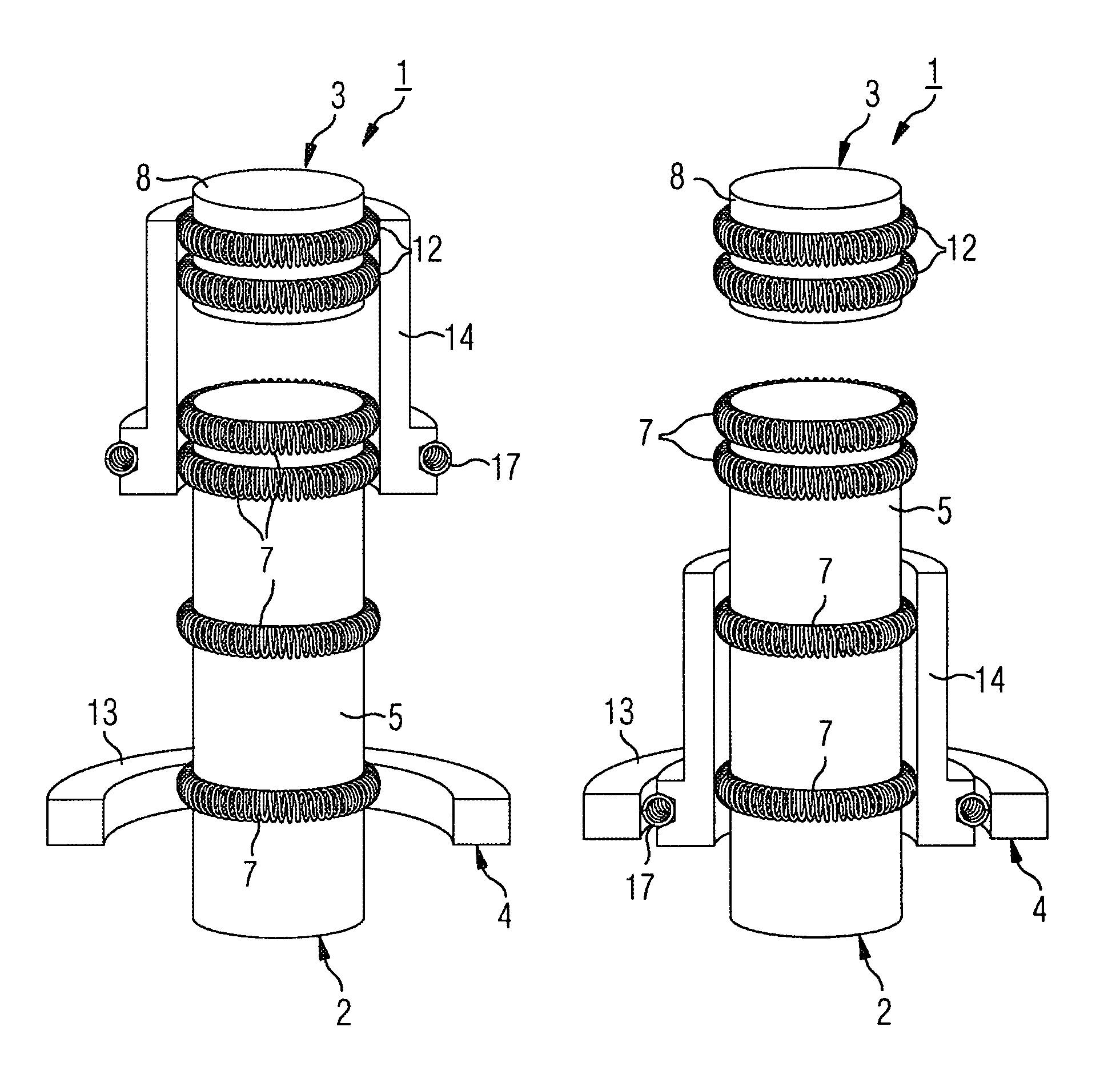
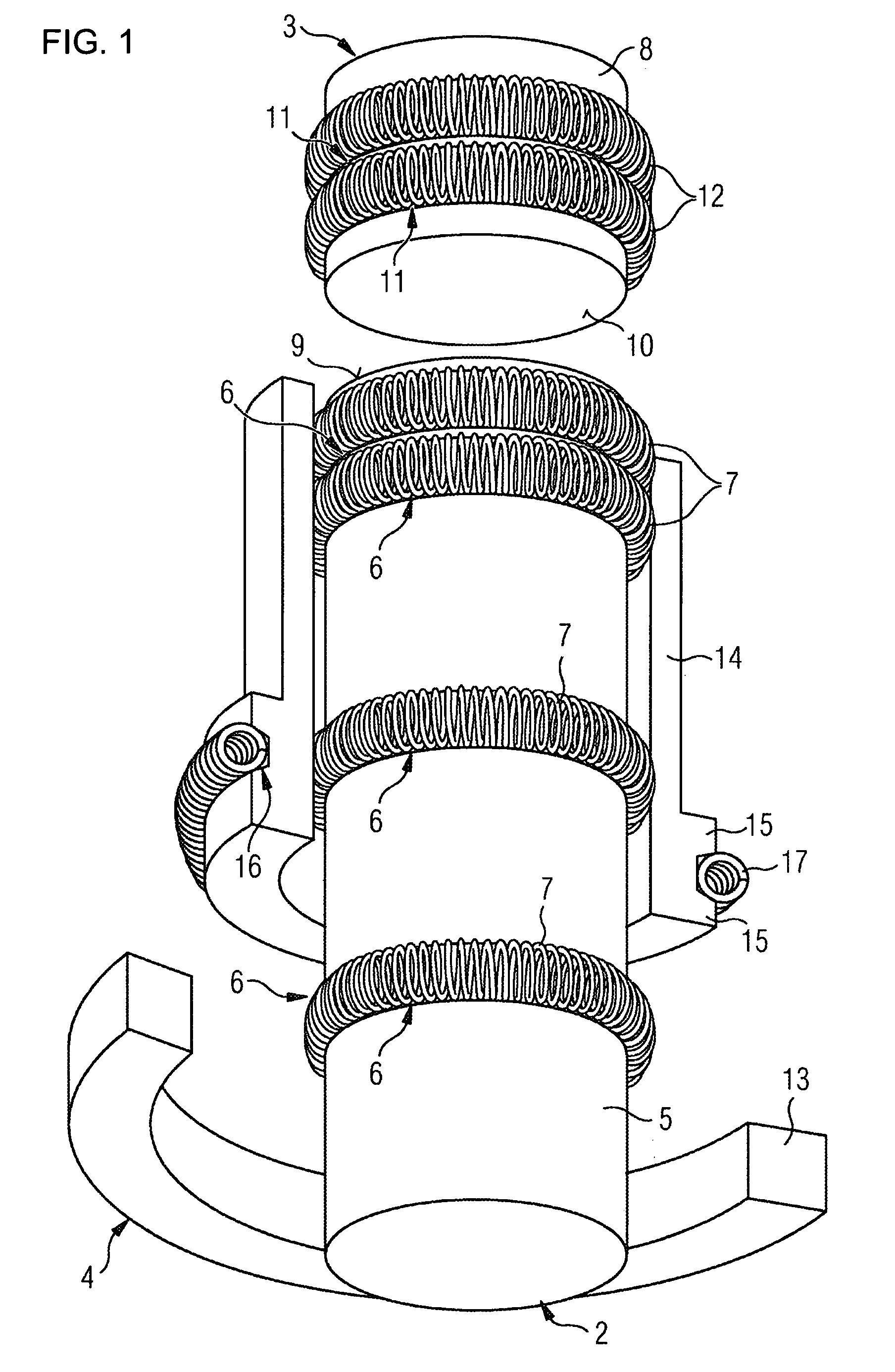
[0026]FIG. 1 shows a schematic, partially sectioned illustration of a first exemplary embodiment of a switch disconnector 1 according to the invention. The switch disconnector 1 is in this case a so-called three-position switch, which can be used in particular for power supply and distribution in gas-insulated medium-voltage assemblies. The switch disconnector 1 has a first connection 2, which is used for connecting the switch disconnector 1 to a circuit breaker, and a second connection 3, which is used for connecting the switch disconnector 1 to a busbar. The switch disconnector 1 also contains a third connection 4 for connecting the switch disconnector 1 to a ground potential.
[0027]The first connection 2 has a cylindrical, elongate pin 5, with a plurality of annular cutouts or grooves 6 being introduced into the surface of said pi...
PUM
 Abstract
Description
Claims
Application Information