Apparatus for testing a protective measuring or metering device as a constituent part of a high or medium voltage installation, more specifically of a utility protective relay, of a generator protective device, of a current meter, or of other protective, measuring or metering electrical devices in a high or medium voltage installation

a technology for measuring or metering devices, which is applied to measuring devices, dynamo-electric motor meters, instruments, etc., can solve the problems clamps that did not provide any pull relief, and wiring that is more manageable, so as to reduce the possibility of failure and save a significant portion of space. , the effect of limiting the possibility of failur

Active Publication Date: 2011-02-08
OSTMEIER HUBERT
View PDF14 Cites 4 Cited by
  • Summary
  • Abstract
  • Description
  • Claims
  • Application Information

AI Technical Summary

Benefits of technology

[0011]It is therefore an object of the invention to remedy the high-cost erection, mounting, and monitoring problems associated with cabling between the input fields and protective fields of high and medium voltage installations. More specifically, it intends to remove the need for separate blocks with respective terminal and pole functions, and thereby make wiring more manageable and limit the possibilities of failure as a result thereof. Additionally, by combining the functions of two separate blocks into one and providing the capability of mounting on a rail located for example at the rear of the electrical panel into which such devices are installed the invention will allow the user to save a significant portion of space in the panel and thereby provide more space for the installation of other devices, if desired. Considering these benefits together, the invention saves users a significant amount of installation and operating costs by reducing the need for wiring and providing more space for other devices.

Problems solved by technology

More specifically, it intends to remove the need for separate blocks with respective terminal and pole functions, and thereby make wiring more manageable and limit the possibilities of failure as a result thereof.
According to prior art as cited in DE 10 2005 025 108, there was provided for a pole block also comprising cable clamps, but these cable clamps did not provide any pull relief due to their arrangement and configuration.
This is undesirable since, when the contact strips no longer act onto the pole blades of the plug with the required force, a permanent electrical connection for testing a utility protective relay for example might not be maintained.

Method used


Image

  • Apparatus for testing a protective measuring or metering device as a constituent part of a high or medium voltage installation, more specifically of a utility protective relay, of a generator protective device, of a current meter, or of other protective, measuring or metering electrical devices in a high or medium voltage installation
  • Apparatus for testing a protective measuring or metering device as a constituent part of a high or medium voltage installation, more specifically of a utility protective relay, of a generator protective device, of a current meter, or of other protective, measuring or metering electrical devices in a high or medium voltage installation
  • Apparatus for testing a protective measuring or metering device as a constituent part of a high or medium voltage installation, more specifically of a utility protective relay, of a generator protective device, of a current meter, or of other protective, measuring or metering electrical devices in a high or medium voltage installation

Examples


Embodiment Construction

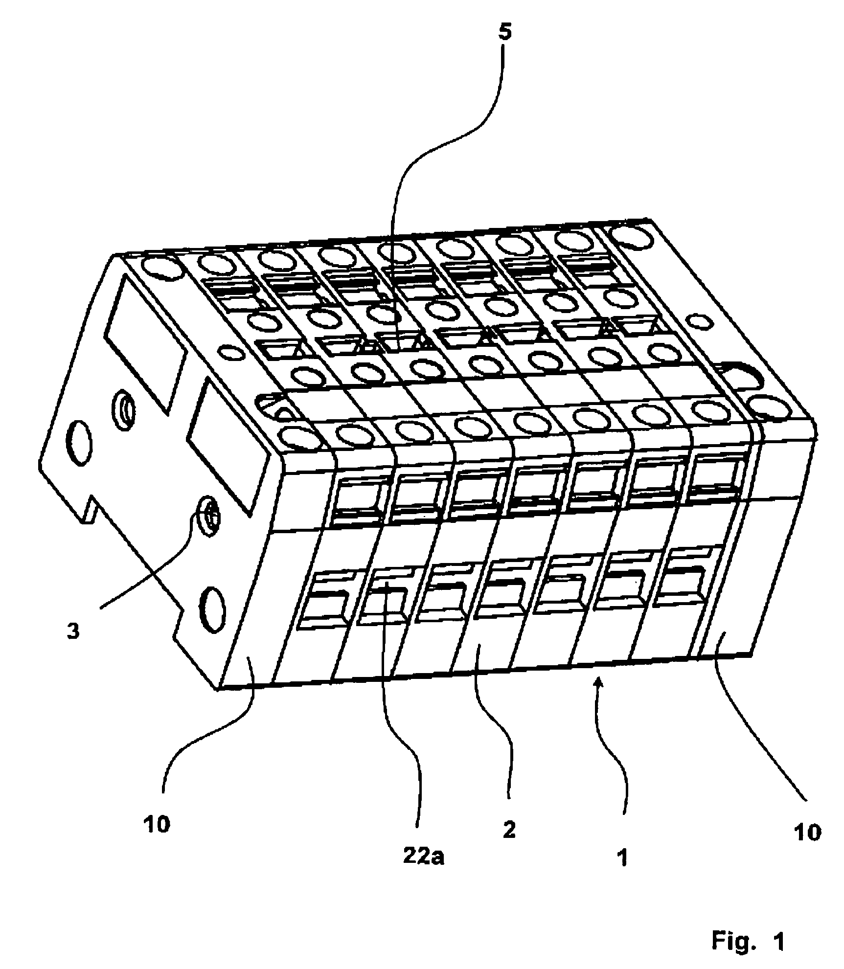
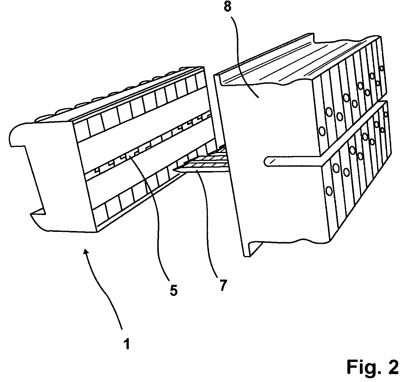
[0021]According to FIG. 1, the particular terminal and pole block shown therein and indicated at 1 consists in all of seven terminal and pole segments 2. The terminal and pole segments 2 are joined together by screws (not shown) that project through the holes 3. At the end of the terminal and pole block there are located head segments 10 that will be discussed herein after. The terminal and pole block indicated at 1 has on its upper side pole openings 5 serving to accommodate the pole blades 7 of a pole plug indicated at 8 (FIG. 2). The pole plug 81 and pole block 1, serves for example to bypass a utility protective relay, or to connect checking devices for checking this utility protective relay to which the terminal and pole block 1 is connected. This has already been discussed above.

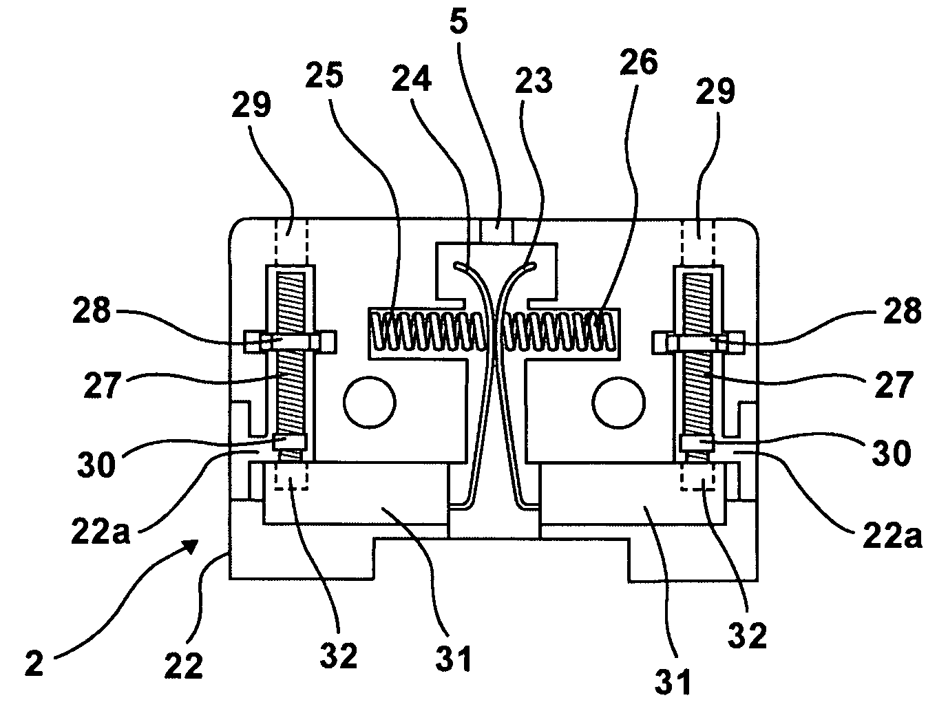
[0022]The actual object of the invention is the configuration of the terminal and pole segments 2 as shown in FIG. 3. The terminal and pole segment 2 shown in FIG. 3 has a housing 22, two contact blade...


PUM


Abstract

The subject matter of the invention is an apparatus for testing a protective, measuring or metering device as a constituent part of a high or medium voltage installation, more specifically of a utility protective relay, of a generator protective device, of a current meter and so on in a high or medium voltage installation, a combined terminal and pole block (1) located in the input field of the high or medium voltage installation being connected in the protective field to the protective, measuring or metering device, said terminal and pole block (1) comprising several terminal and pole segments (2) disposed behind each other, each terminal and pole segment (2) comprising on its upper side a pole opening (5) for receiving the pole blade (7) of a plug (8), each terminal and pole segment (2) having a cable clamping apparatus (27; 31) on either side thereof, said cable clamping apparatus (27; 31) being accessible through an opening (22a) for the cable disposed in the side wall of the terminal and pole segment (2).

Description

1. FIELD OF THE INVENTION[0001]The present invention relates to an apparatus for testing a protective, measuring or metering device as a constituent part of a high or medium voltage installation, more specifically or a utility protective relay, of a generator protective device, of a current meter or of other protective, measuring or metering electrical devices in a high or medium voltage installation.2. DESCRIPTION OF THE PRIOR ART[0002]A terminal block for a current meter is known from DE 102 16 913 terminal clamp members being provided for plugging onto the current meter. This allows for exchanging a meter without interrupting the current supply by plugging a bypass plug onto the terminal block.[0003]A high voltage installation is meant to refer e.g., to 110 kV installations in an electrical substation. With such a 110 kV installation, the current supply occurs via corresponding 110 kV lines. When one phase fails in such a 110 kV line, the line must be completely shut off. Relays,...

Claims


Application Information

Patent Timeline
Patent Type & Authority Patents(United States)
IPC IPC(8): G01R1/00
CPCG01R31/327
Inventor OSTMEIER, HUBERT
Owner OSTMEIER HUBERT
Why Eureka
Try Eureka