
Process for determining and providing run time information for robot control programs

a robot control and run time information technology, applied in the direction of programme-controlled manipulators, specific program execution arrangements, program control, etc., can solve the problems of high accuracy of measurement, unambiguous statement of measurement, and erroneous or non-optimal programming

Inactive Publication Date: 2011-02-08
KUKA ROBOTER
View PDF14 Cites 0 Cited by
  • Summary
  • Abstract
  • Description
  • Claims
  • Application Information

AI Technical Summary

Benefits of technology

[0006]Based on the drawbacks described above, the basic object of the present invention is to provide a process for providing run time information for computer programs for controlling industrial robots in such a way that run time measurements are possible on the robot control program without distortion of the run time characteristic of the robot control program with the most accurate assignment possible of code sections of the robot control program to the time measurements performed.
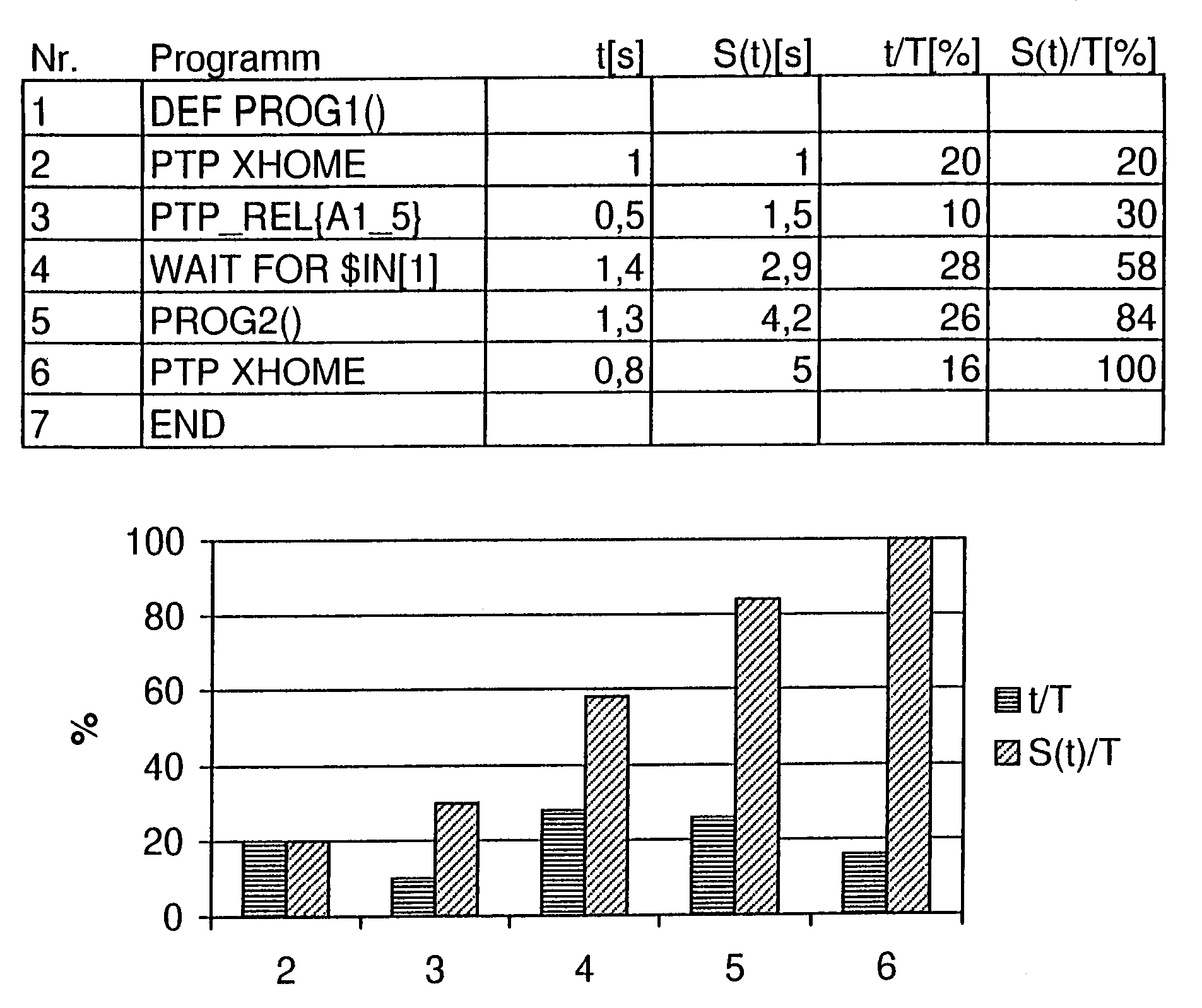
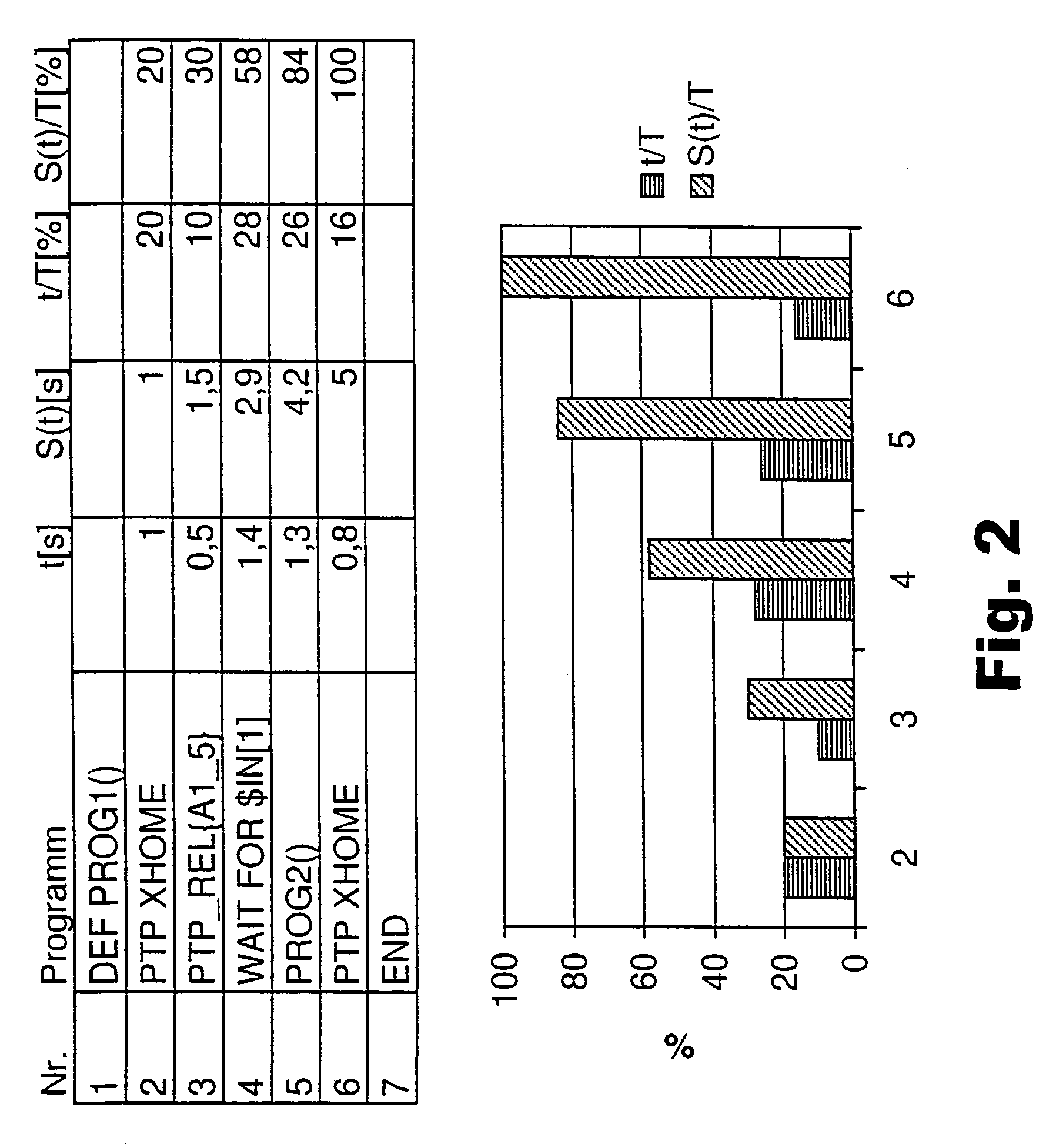
[0011]According to the present invention, the process makes possible the logging of the execution times of individual commands and / or subroutines of a running robot control program without any loss of run time due to additional commands in the program itself. The robot control program does not need to be changed by additional commands for the run time determination according to the process being proposed. Furthermore, the use of the process according to the present invention also does not lead to a deterioration of the cycle time within the framework of the measurement operation, because the interpreter, i.e., the program used to translate the control program source code, which is usually written in a higher program language, into the machine language must process the individual commands or subroutines anyway in the course of the execution of the program, so that the access times can be directly derived from this. According to the present invention, the time period for executing the individual command or subroutine is recorded only implicitly by the storage of the beginning and end system time, and the duration of the storage operation is insignificant in relation to the duration of the command or subroutine.
[0013]Since a subroutine is composed by definition of a number of individual commands, it is possible, in particular, for a subroutine to contain a command by which it will again (partially) call itself recursively in the nested form, i.e., in the form of a loop, or for a first subroutine to call a second, other subroutine. The number of callings thus nested is called depth of recursion. To make it possible to subsequently infer the actual duration of an individual execution of the subroutine during an evaluation from the measured (overall) run time for a recursive subroutine, provisions are made according to a preferred variant of the process according to the present invention for a value of a depth of recursion to be additionally determined for subroutines. The actual run time of the subroutine can thus be calculated from the difference of the determined system times in conjunction with the depth of recursion.

Problems solved by technology

This is linked, on the one hand, with the different frequency with which certain commands or subroutines are called, but, on the other hand, also with the internal complexity of these commands and subroutines, which complexity may be inherently given, on the one hand, e.g., in case of certain arithmetic operations such as root operations, but may also result, on the other hand, from an erroneous or non-optimal programming.
However, the result of such a measurement is highly inaccurate due to the process and, moreover, only slightly detailed, because it cannot usually be recognized from the outside in which concrete individual command or subroutine the robot control happens to be during the execution of the control program running on it.
It proved to be disadvantageous here, in particular, that due to the insertion of additional program code in the robot control program, the time characteristic of the robot control program, which is to be determined, is changed per se, so that no unambiguous statement can be made from the measuring results obtained on the actual run time characteristic of the robot control program being checked.

Method used


Image

  • Process for determining and providing run time information for robot control programs
  • Process for determining and providing run time information for robot control programs
  • Process for determining and providing run time information for robot control programs

Examples


example

[0027]

DEF P1 ( )INT A; integer AA=FAKULTAET (5)ENDDEF FAKULTAET (INT F)IF F>1 THENRETURN (F*FAKULTAET (F−1)); crossed calling of SR “Fakultat”ENDIFRETURN (1)END

Calling Hierarchy (Subroutine FAKULTAET is Designated Here by F for Short): F(5)->F(4)->F(3)->F(2)->F(1)

Depth of Recursion R:

[0028]

01234

Execution Time [μsec]:

[0029]

97531

Delta Execution Time [μsec]:

[0030]

2222

[0031]The overall duration for the calculation of the Fakultät is 9 μsec in the example, and a simple calculation takes 2 μsec, and the Fakultat requires 1 μsec at the lowest level, because FAKULTAET (1) can be calculated the fastest (the return value 1 is returned).

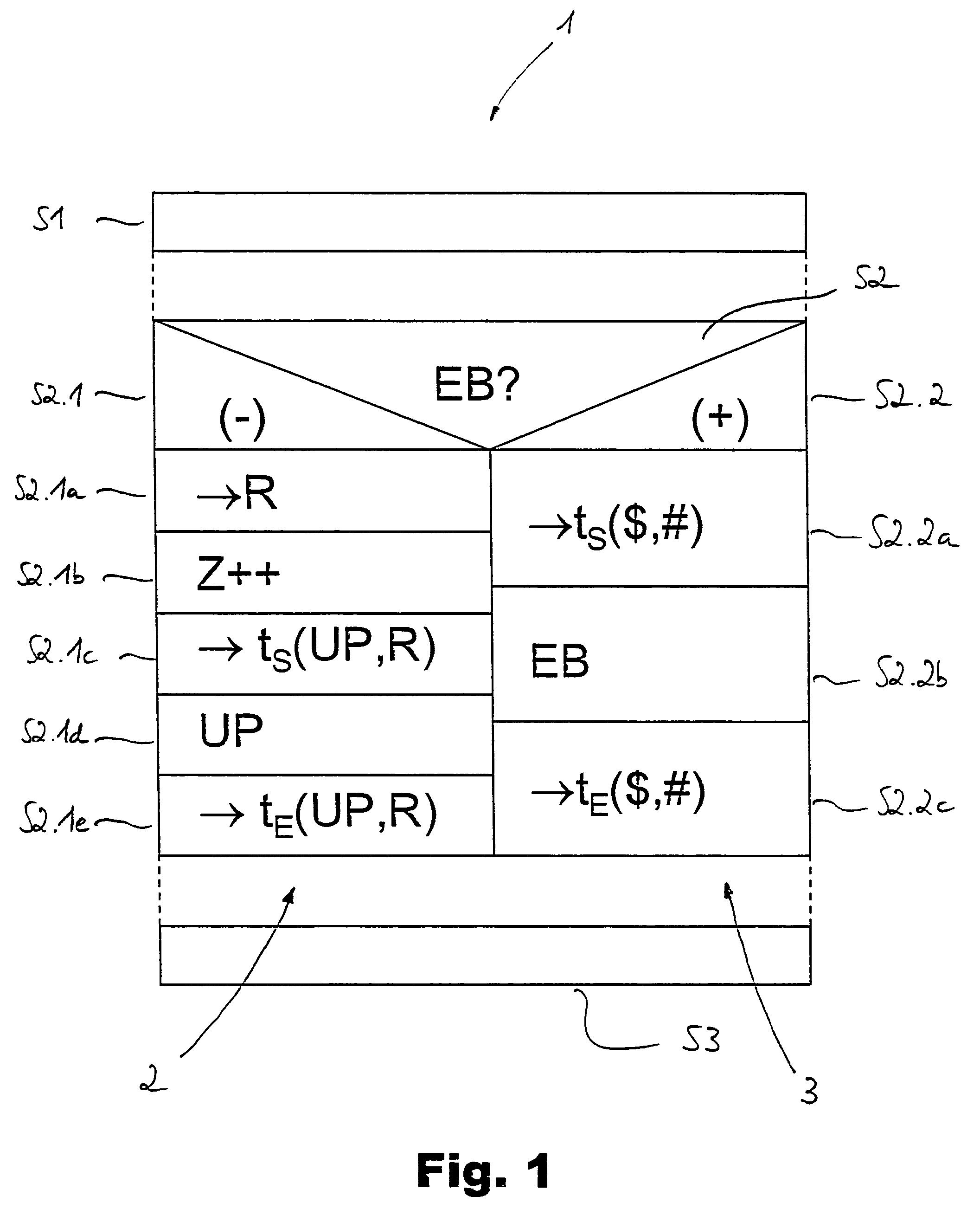
[0032]The value R for the depth of recursion of the subroutine SR is first stored according to the present invention in step S2.1a. The counter Z is then incremented in step S2.1b, which shows how often the subroutine was executed. The notation “Z++” designates an increase in the counter value by 1, i.e., Z->Z+1. An initial system time ts for the execution of t...


PUM


Abstract

In a process for providing run time information for computer programs for controlling industrial robots (robot control programs), a first system time of a computer system executing the program is determined after the calling and before the execution of an individual command or a sequence of individual commands (subroutine). The individual command or the subroutine is subsequently executed, and a second system time of the computer system is determined after the execution. The determination of the system times is carried out on the basis of access times to certain areas of a program memory of the computer system, which areas characterize the individual commands or the subroutine. It is thus possible to carry out run time measurements on robot control programs in a simple and efficient manner, and the results of these run time measurements can be used to optimize such programs.

Description

CROSS REFERENCE TO RELATED APPLICATIONS[0001]This application claims the benefit of priority under 35 U.S.C. §119 of DE103 49 349.2 filed Oct. 23, 2003, the entire contents of which are incorporated herein by reference.FIELD OF THE INVENTION[0002]The present invention pertains to a process for providing run time information for computer programs for controlling industrial robots.BACKGROUND OF THE INVENTION[0003]Programmable control units, which are designed such that application- and user-specific computer programs can run on them for controlling industrial robots (robot control programs), are usually used to control industrial robots. Such control programs are usually prepared by a user, a robot programmer, and they contain a number of individual commands or sequences of individual commands in the form of procedures or subroutines, via which the motor mechanism of the robot is acted on within the framework of a motion control. The individual commands and the subroutines built up fr...

Claims


Application Information

Patent Timeline
Patent Type & Authority Patents(United States)
IPC IPC(8): G06F9/44B25J9/16G05B19/042
CPCB25J9/1656G05B19/0426G05B2219/39068
Inventor GROB, FRANZ
Owner KUKA ROBOTER
Learn More