
Gas turbine engine

a technology of gas turbine engines and turbine engines, which is applied in the direction of marine propulsion, vessel construction, aircraft navigation control, etc., can solve the problems of reducing the flow rate of gas turbine engines, affecting the operation of drag effects within the zone b>11/b>, and reducing the thrust recovery from the vent zone b>, so as to facilitate static pressure reduction in the fluid flow

Inactive Publication Date: 2011-02-15
ROLLS ROYCE PLC
View PDF12 Cites 64 Cited by
  • Summary
  • Abstract
  • Description
  • Claims
  • Application Information

AI Technical Summary

Benefits of technology

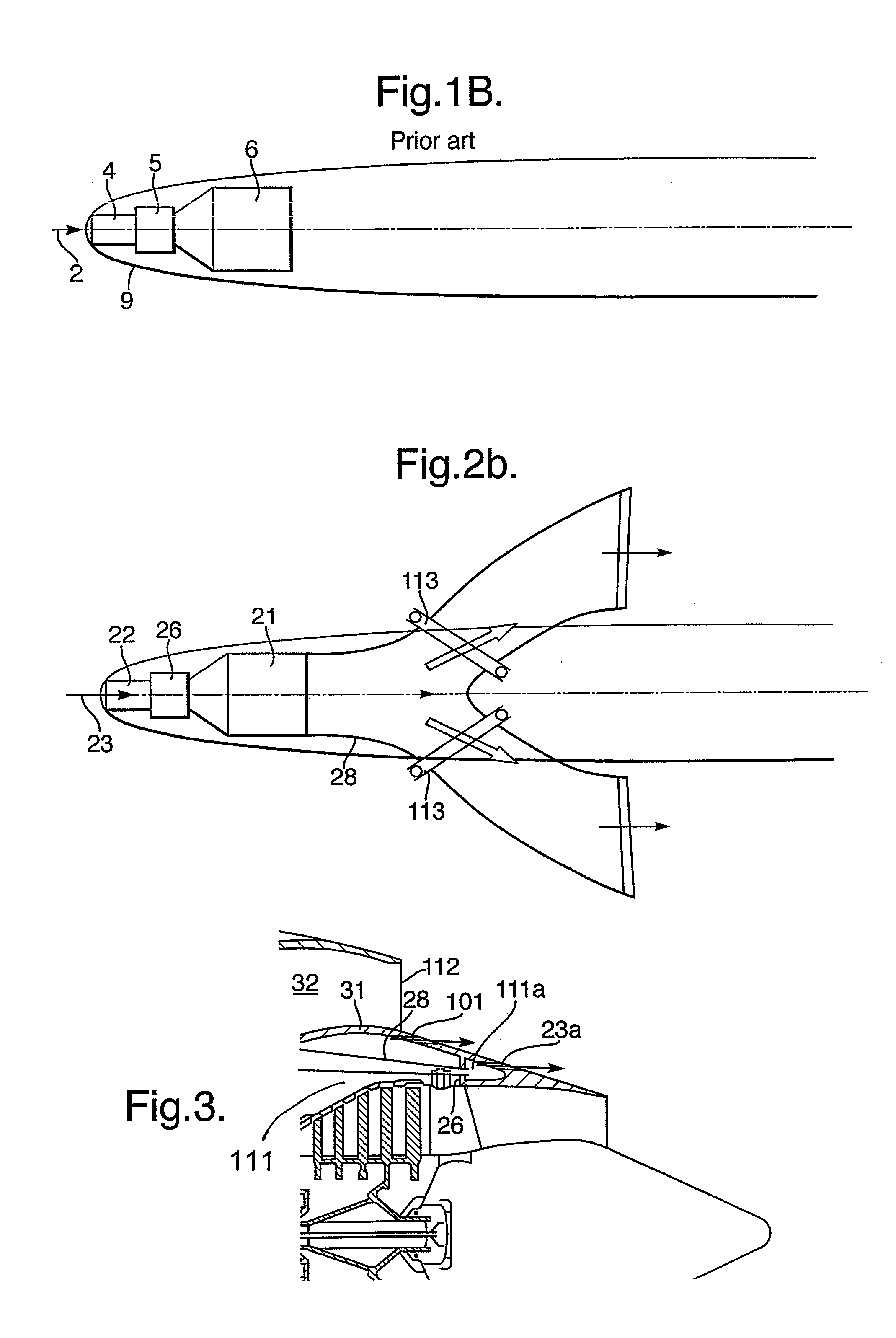
[0010]Typically, the outlet duct has a converging nozzle to facilitate static pressure reduction in a fluid flow.
[0012]Potentially, the outlet duct has a baffle to facilitate static pressure reduction in the fluid flow.

Problems solved by technology

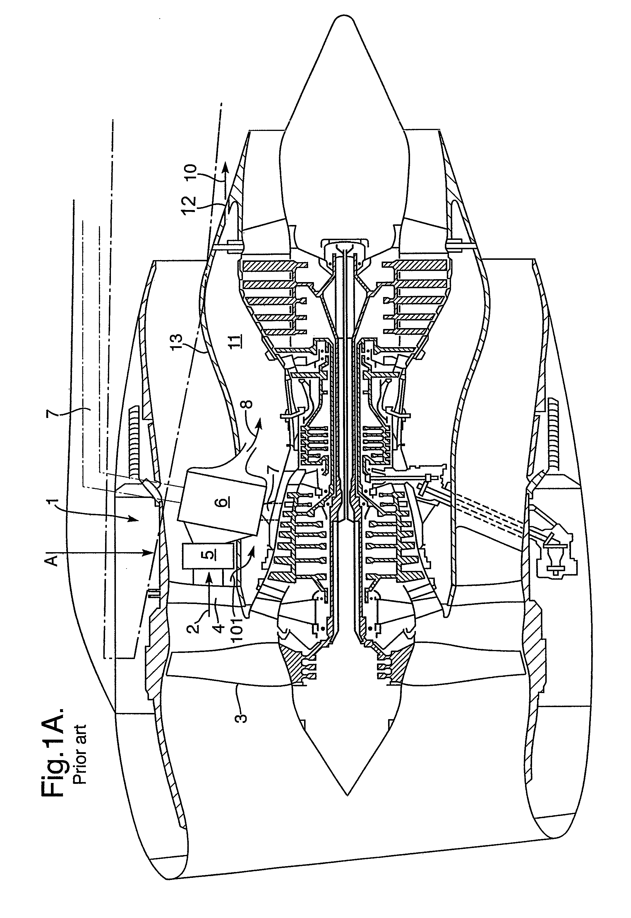
Such an approach has a number of problems including increase in the temperature in the zone 11 and as a result of the large exit area results in a drag effect within the zone 11 detrimental to operation.
Furthermore, thrust recovery is compromised from the vent zone 11 in view of the size of the vent 12 which is effectively over-sized through normal operation for the reasons described above.
A further disadvantage as indicated above is that there is extra heat input to the zone 11 which may require considerable shielding and heat resistant cabling within the core 13.

Method used


Image

  • Gas turbine engine
  • Gas turbine engine
  • Gas turbine engine

Examples


Embodiment Construction

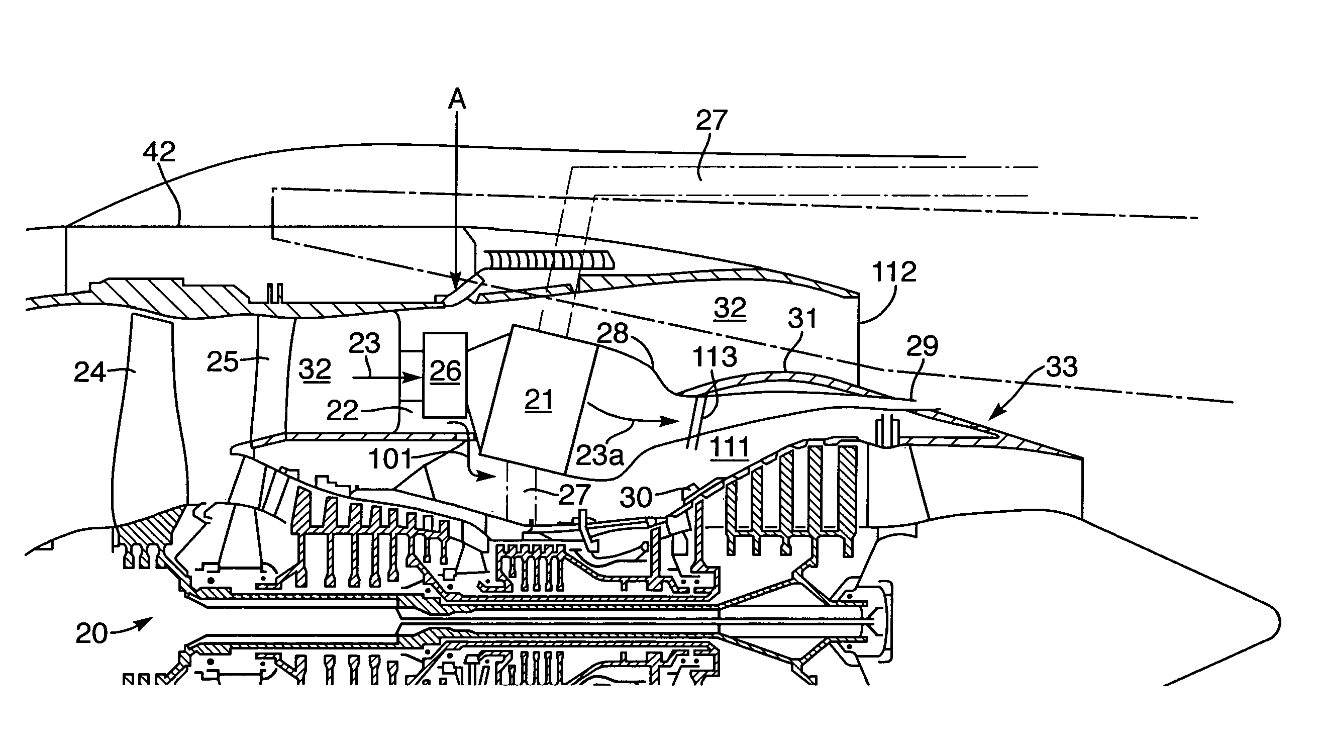
[0027]As indicated above, heat exchangers in accordance with aspects of the present invention are utilised within a gas turbine engine in order to provide cooling for compressed air flows utilised for cabin ventilation or other functions. In such circumstances it is important that an adequate pressure drop across the heat exchanger is maintained such that a fluid flow presented as a coolant to the heat exchanger will pass through the heat exchanger in order to cool the compressed air flows appropriately. Exhausting of that fluid flow passed through the heat exchanger creates the problems outlined above but nevertheless maintenance of an adequate pressure differential is essential.

[0028]In accordance with aspects of the present invention a dedicated, independent outlet ducting for the exhaust fluid flow from the heat exchanger is provided. This dedicated outlet ducting acts as a conduit for the exhaust fluid flow from the heat exchanger to a location where there is ambient or low sta...


PUM


Abstract

Within a turbine engine a heat exchanger may be provided to cool compressor air flows to be utilized for cabin ventilation or other functions. A fluid flow acting as a coolant for the heat exchanger is generally drawn from the by-pass duct of the engine and a dedicated outlet duct is provided such that the exhausted fluid flow from the heat exchanger is delivered along the conduit duct to a low pressure region. In such circumstances, an appropriate pressure differential across the heat exchanger is maintained for operational efficiency when required, whilst the exhausted fluid flow is isolated and does not compromise the usual engine ventilation vent exit area sizing. Over-sized ventilation vents would create an aerodynamic step and therefore drag upon the thrust of the engine. Typically, the outlet end of the outlet duct has a variable geometry to enable adjustment in the pressure differential across the heat exchanger such that an air fan valve used to control flow rate through the heat exchanger may not be required.

Description

CROSS-REFERENCE TO RELATED APPLICATIONS[0001]This application claims priority to GB 0607773.9, filed 20 Apr. 2006 now granted United Kingdom patent GB 2,438,696.BACKGROUND OF THE INVENTION[0002]The present invention relates to gas turbine engines (gas or steam) and more particularly to heat exchanger arrangements within such turbine engines utilised to provide ventilation air or for cooling of other fluids such as fuel or oil or compressed air utilised for de-icing.[0003]FIG. 1a is a schematic side view of an engine showing a prior art heat exchanger arrangement and FIG. 1b is a plan view in the direction of arrowhead A of the engine and in particular the heat exchanger arrangement as depicted in FIG. 1a; Compressed air bled from the compressor stages of a gas turbine engine is utilised to provide ventilation air within the cabin of an aircraft associated with a gas turbine engine. This air must be cooled for acceptability with respect to such ventilation or other functions. Typical...

Claims


Application Information

Patent Timeline
IPC IPC(8): F02K99/00F02K3/02
CPCF01D17/105F01D17/148F02C3/13F02C6/08F02C7/141F02C7/18F02C7/185B64D2033/024Y02T50/675Y02T50/60F01D25/08F02C3/04F02C7/14F02K3/025F02K3/06F02K3/115
Inventor STRETTON, RICHARD GZAKRZEWSKI, PAWEL R
Owner ROLLS ROYCE PLC
Learn More