Method and devices for reducing vibration

a technology of vibration reduction and reducing path, which is applied in the direction of office printing, printing, rotary presses, etc., can solve the problem of increasing the mode caused by the actuator, and achieve the effect of simple mounting and short actuating path

Inactive Publication Date: 2011-02-15
KOENIG & BAUER AG
View PDF27 Cites 0 Cited by
  • Summary
  • Abstract
  • Description
  • Claims
  • Application Information

AI Technical Summary

Benefits of technology

[0012]The advantages which can be obtained by the present invention consist, in particular, in that the required rapid reaction times and high dynamics are achieved by the pre-control with a predefined force progression. By the predetermination of a signal course, which is matched to the groove beat, of the force push that is to be generated by the actuator, only a matching of the signal strength is required.
[0013]It is also of great advantage that, besides the groove beat, the excitation by the actuator itself is included in the calculation algorithm. It is possible by the use of this, to reduce the vibrations as a whole, i.e. to also reduce modes of vibration which are caused by the actuator itself. Otherwise, there is the danger that, although a characteristic mode of the cylinder vibration, which is caused by the groove beat is reduced, a mode which is caused by the actuator is increased.
[0016]A configuration of a bearing arrangement, in which the respective cylinder can be placed against or away from a second cylinder in linear bearings, is of particular advantage in view of short actuating paths and simple mounting. In this case, the linear bearing elements, the rotary bearing, as well as the actuator which compensates for vibrations, are preferably arranged as a module in a bearing unit which can be mounted as a unit.

Problems solved by technology

Otherwise, there is the danger that, although a characteristic mode of the cylinder vibration, which is caused by the groove beat is reduced, a mode which is caused by the actuator is increased.

Method used


Image

  • Method and devices for reducing vibration
  • Method and devices for reducing vibration
  • Method and devices for reducing vibration

Examples


first embodiment

[0057]Thus, different actuators 21, 23 are provided in the first embodiment, on the one hand for the contact / out of contact movement, an actuator 21 which is embodied as an actuating drive 21, and on the other hand an actuator 23 for vibration compensation

[0058]The actuators 23 are in signal connection with a regulating and / or control arrangement 57, such as, for example, an adaptive control device 57, which is schematically represented in dashed lines in FIG. 12.

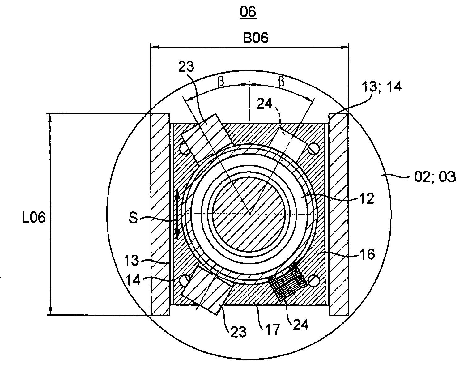
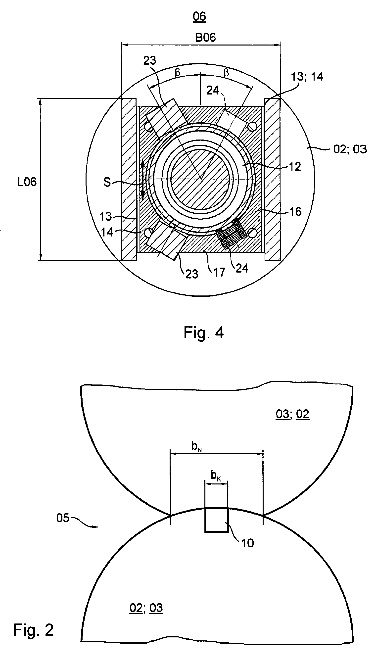
[0059]FIGS. 6 and 7 show a second preferred embodiment of an advantageous bearing unit 06, based on linear actuating paths, and shown in longitudinal and cross section, respectively. The bearing unit 06 into which the cylinder contact / out of contact mechanism is integrated has, besides a radial bearing 12, for example a cylinder roller bearing 12 for the rotatory seating of the cylinder 02, 03, and seating bearing elements 13, 14 for a radial movement of the cylinder 02, 03, for print-on, or print-off, setting. For this pur...

second embodiment

[0078]Thus, in the second embodiment the same actuators 31 are provided for the into / out of contact movement, on the one hand, and for vibration compensation on the other hand.

[0079]In a modified embodiment of a double printing group 01 which is arranged angled, such as an- or u-printing group 01, it is intended to consider the plane E′ to be the connecting plane of the cylinders 02 forming the print position, and the plane E″ to be the connecting plane between forme and transfer cylinders 02, 03, and what was stated above in regard to the angle β is to be applied to the actuating direction S of at least one of the cylinders 02 forming the print position, or the forme cylinder 03 and the plane E′, or respectively E″.

[0080]One of the cylinders 02 which is forming the print position however, can also be arranged, fixed in place and operationally non-actuable, but adjustable, if required in the lateral frame 07, 08, while the other is seated along the actuating direction S.

[0081]In ord...

third embodiment

[0088]In the present invention, as depicted in FIGS. 9 and 10, a bearing arrangement 42 for receiving the journals 09 of the cylinders 02, 03 is embodied as a customary radial bearing 42, for example a multi-ring radial bearing 42, which is arranged on or in the lateral frame 07, 08. The bearing arrangement 42 can be embodied as an eccentric bearing for the purpose of placement of the supported cylinders into and out of contact, wherein the shaft of the seated cylinder 02, 03 is displaced in the radial direction by pivoting an eccentric outer ring of the seated cylinder 02, 03. This occurs, for example, by the use of a drive mechanism, which is not specifically represented, such as, for example, an actuating drive for the into / out of contact position, such as mechanically or pneumatically, for example, via appropriate gears. The bearing arrangement 42 has at least one ring 43, divided in FIGS. 9 and 10, such as, for example, an eccentric intermediate ring 43, and at least one ring 4...


PUM


Abstract

Vibrations of a cylinder, which is a part of a web-processing machine, and particularly a printing machine, are dampened. A functional correlation is determined for a course of a force of a channel passage through a nip point defined by the cylinder and a second cylinder. The functional correlation is pre-defined up to a scaling factor determining the height as a time course for an actuator force time course and is stored in a control or a regulating device. The vibration, or an amplitude of the vibration is measured during the operation of at least part of the cylinder by the use of a sensor. A maximum vibration amplitude on the roll body of the cylinder is then calculated from the measuring value. The actuators are controlled by the control or regulating device according to the pre-defined actuator force time course.

Description

CROSS-REFERENCE TO RELATED APPLICATIONS[0001]This application is the U.S. national phase, under 35 USC 371, of PCT / EP2005 / 056644, filed Dec. 9, 2005; published as WO 2006 / 061432 A1 on Jun. 15, 2006, and claiming priority to DE 10 2004 059 849.5, filed Dec. 10, 2004, the disclosures of which are expressly incorporated herein by reference.FIELD OF THE INVENTION[0002]The present invention is directed to a method and to devices for vibration reduction. Vibration is reduced in a cylinder of a web-processing machine. At least one actuator acts on the cylinder, or on a journal for the cylinder.BACKGROUND OF THE INVENTION[0003]A method and a device for reducing vibrations is known from DE 102 53 997 C1. A raised portion, in the area of the shell face, of a rotating component can be changed in its height and / or in its position.[0004]WO 03 / 064763 A1 discloses a method and a device for reducing vibrations. Journals and / or bearings are acted upon by actuators. In this case, a signal path, which...

Claims


Application Information

Patent Timeline
Patent Type & Authority Patents(United States)
IPC IPC(8): B41F13/26
CPCB41F13/085F16F15/02
Inventor CHRISTEL, RALFHAHN, OLIVER FRANKSCHASCHEK, KARL ERICH ALBERT
Owner KOENIG & BAUER AG
Why Eureka
Try Eureka