Electric vehicle

a technology for electric vehicles and battery units, applied in the field of electric vehicles, can solve the problems of reducing the possibility of a collision between the battery units, and achieve the effects of preventing the movement of the power unit towards the battery unit, preventing the damage of the battery unit, and preventing the collision

Active Publication Date: 2011-02-15
MITSUBISHI MOTORS CORP
View PDF14 Cites 64 Cited by
  • Summary
  • Abstract
  • Description
  • Claims
  • Application Information

AI Technical Summary

Benefits of technology

[0011]The present invention has been made in light of the above-mentioned problem. It is an object of the invention to provide an electric vehicle capable of restraining a damage of a battery unit in either case of a collision with a side where a power unit is installed or a collision with a side where the power unit is not installed.

Problems solved by technology

This decreases the possibility of a collision between the battery unit and a broken portion of the bracket portion that remains on the vehicle-body side.

Method used


Image

  • Electric vehicle
  • Electric vehicle
  • Electric vehicle

Examples


Embodiment Construction

[0058]An electric vehicle according to one embodiment of the present invention will be described below in details with reference to FIGS. 1 to 19.

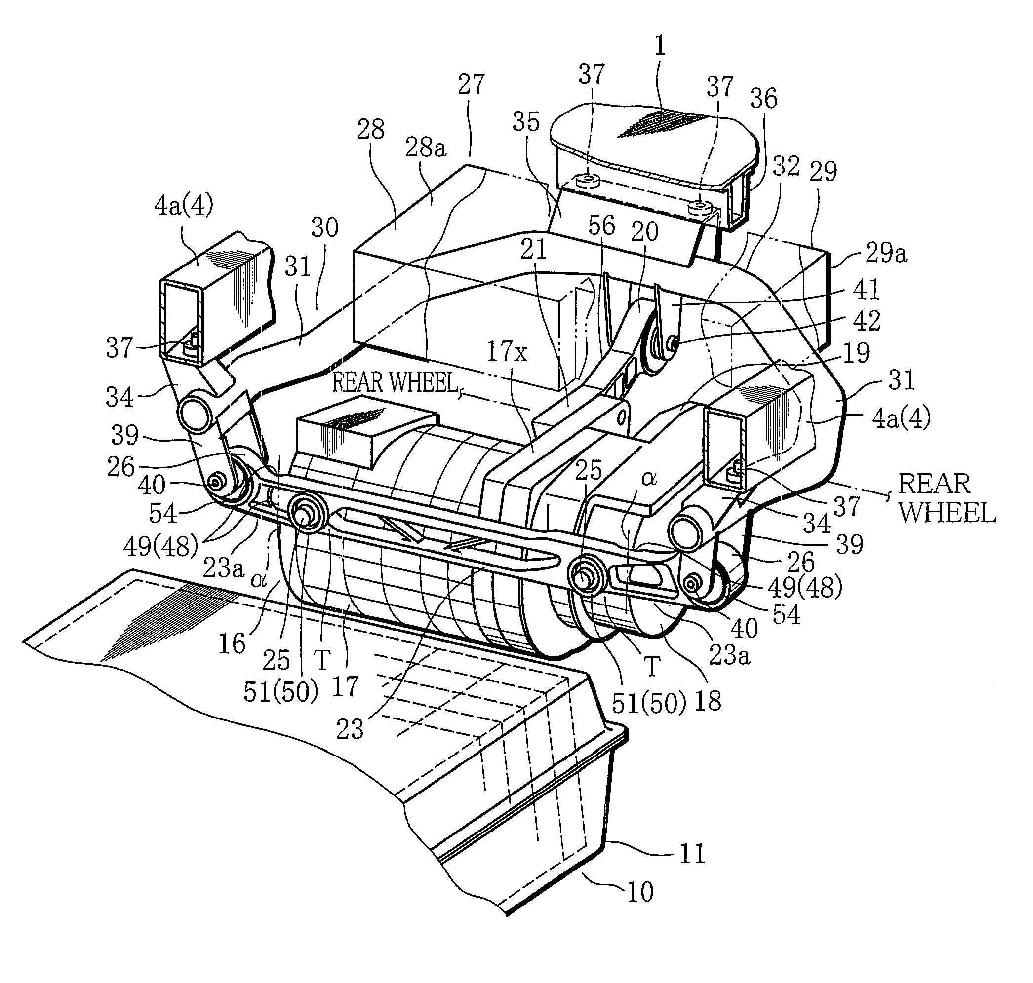
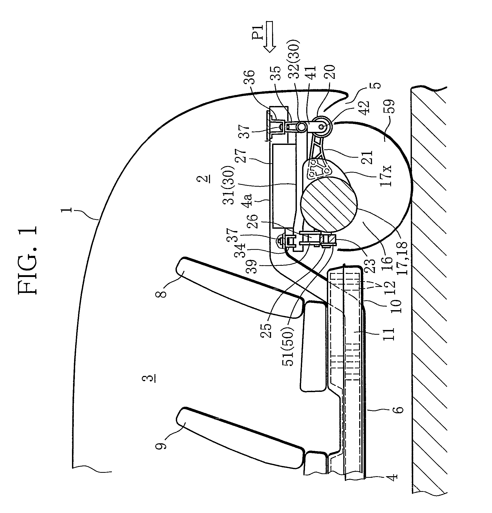
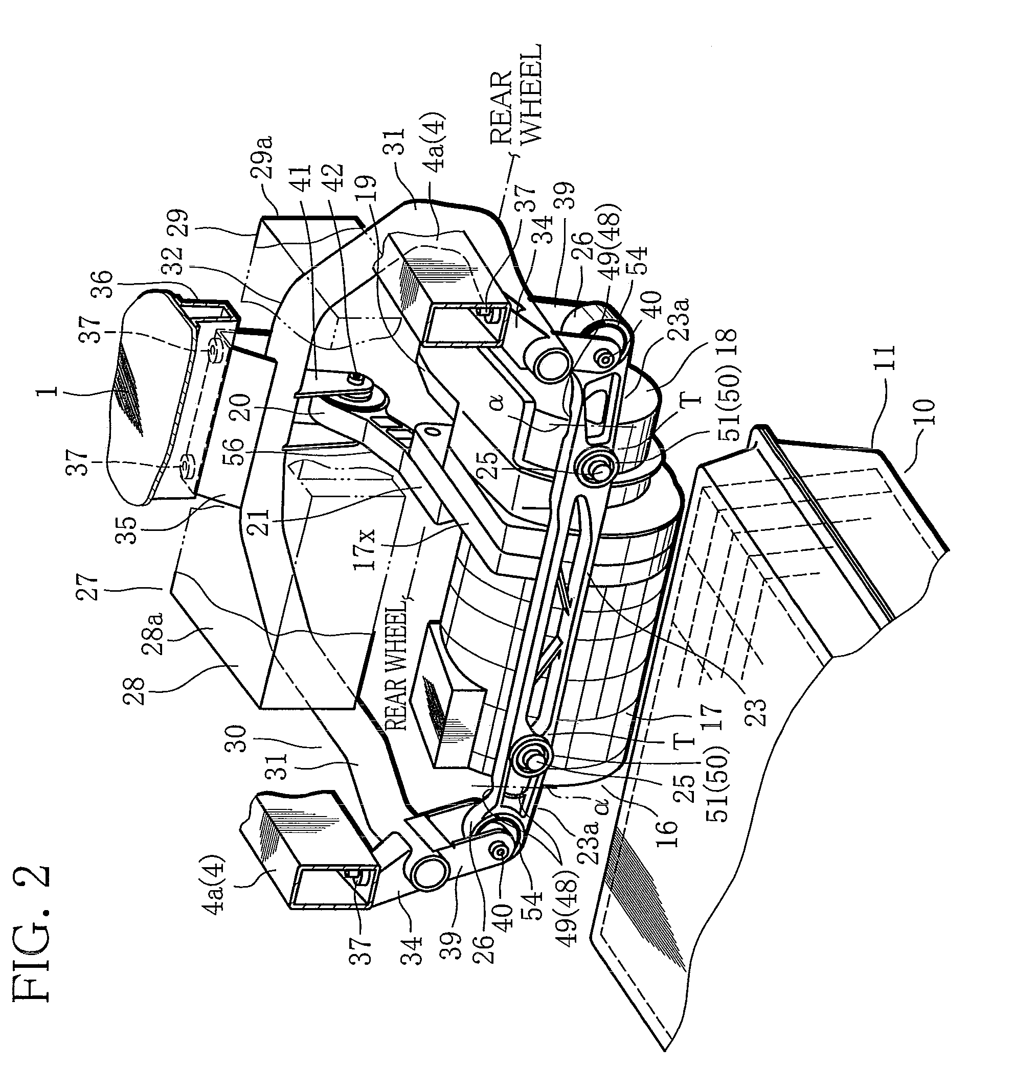
[0059]FIG. 1 is a longitudinal sectional view showing a schematic construction of a rear-portion side of the electric vehicle. In FIG. 1, reference mark 1 represents a vehicle body. The vehicle body 1 has a luggage compartment 2 in a backmost region as considered in a longitudinal direction, and also has a passenger compartment 3 in a central region as considered in a longitudinal direction. Reference mark 4 denotes a pair of side frames placed in a lower face of the vehicle body 1. The side frames 4 make up the frame of the vehicle body 1. As shown in FIG. 2, the two side frames 4 are arranged parallel to each other with a given space therebetween in a width direction of the vehicle. The side frames 4 extend in a longitudinal direction of the vehicle, running under a floor of the passenger compartment 3 and also under a floor of the lugga...


PUM


Abstract

An electric vehicle has a first bracket (23) that supports a battery unit (10)-side end of a power unit (16) and extends in a width direction of the vehicle. The first bracket (23) is coupled to a vehicle body through a first coupling section (26) formed in one end of the first bracket (23) and a second coupling section (26) formed in the other end, and the power unit (16) is coupled to the first bracket (23) through at least two inner coupling sections (24) that are located more inside than the first and second coupling sections (26) as considered in the width direction of the vehicle. A first fragile portion (48) is formed between the first coupling section (26) and the inner coupling section (24) closest to the first coupling section (26), and between the second coupling section (26) and the inner coupling section (24) closest to the second coupling section (26). The first fragile portion (48) is broken by a smaller impact load at the time of collision with the side where the power unit (16) is installed than at the time of collision with the side where the power unit (16) is not installed.

Description

TECHNICAL FIELD[0001]The present invention relates to an electric vehicle equipped with a power unit and a battery unit.BACKGROUND ART[0002]For reliability improvement, cost reduction, and reduction of development time, an electric vehicle may be equipped with a power unit constructed of an electric motor and other parts and a battery unit serving as a power source, using a vehicle body of the vehicle which is designed to be equipped with an internal combustion engine. More specifically, an engine room that is formed on one end side of the vehicle body as considered in a longitudinal direction of the vehicle body is utilized without change as a power unit room for installing the power unit. The battery unit is set under the floor of a passenger compartment situated in the center of the vehicle body.[0003]In general, the power unit of an electric vehicle is supported onto the frame of the power unit room by means of a first bracket protruding sideways from the battery unit-side end o...

Claims


Application Information

Patent Timeline
Patent Type & Authority Patents(United States)
IPC IPC(8): B60K5/00B62D27/00
CPCB60K1/00B60L3/0007B60L11/1877B62D21/155B60K2001/0433Y02T10/7005Y02T10/705B60Y2400/61B60L50/66Y02T10/70B60K5/1216
Inventor NOZAKI, TAKUMATAKEDA, ATSUSHIISOGAI, TOSHIAKI
Owner MITSUBISHI MOTORS CORP
Why Eureka
Try Eureka