Systems and methods for monitoring gas turbine engines

a gas turbine engine and monitoring system technology, applied in the direction of machines/engines, fluid pressure measurement, instruments, etc., can solve the problems of inefficient detecting of debris, time-consuming chemical analysis,

Active Publication Date: 2011-02-15
RTX CORP
View PDF15 Cites 52 Cited by
  • Summary
  • Abstract
  • Description
  • Claims
  • Application Information

AI Technical Summary

Problems solved by technology

However, chemical analysis can be quite time-consuming and typically requires equipment that is used by ground maintenance personnel.
Unfortunately, magnetic chip detectors tend to be relatively inefficient at detecting debris.

Method used


Image

  • Systems and methods for monitoring gas turbine engines
  • Systems and methods for monitoring gas turbine engines
  • Systems and methods for monitoring gas turbine engines

Examples


Embodiment Construction

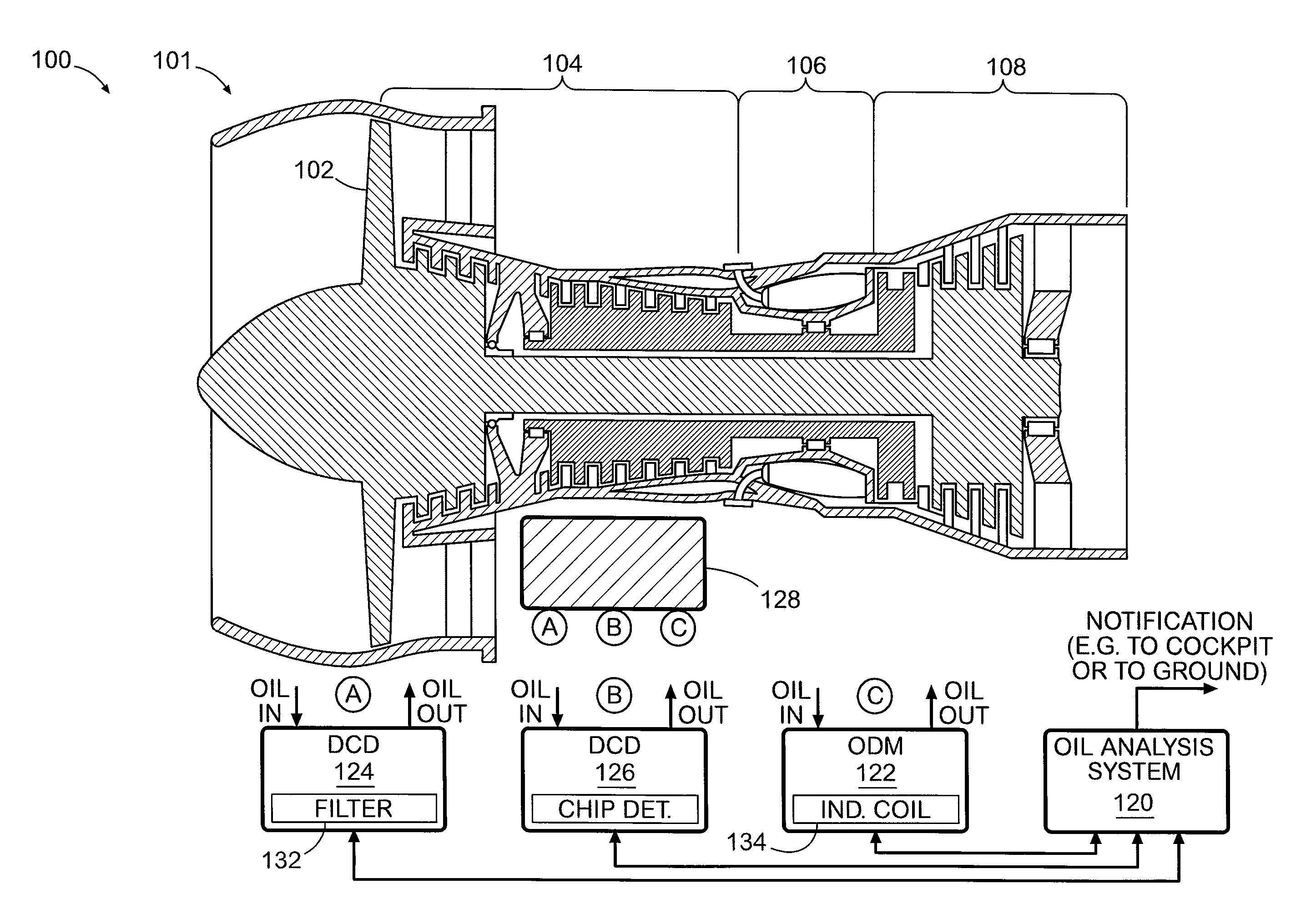
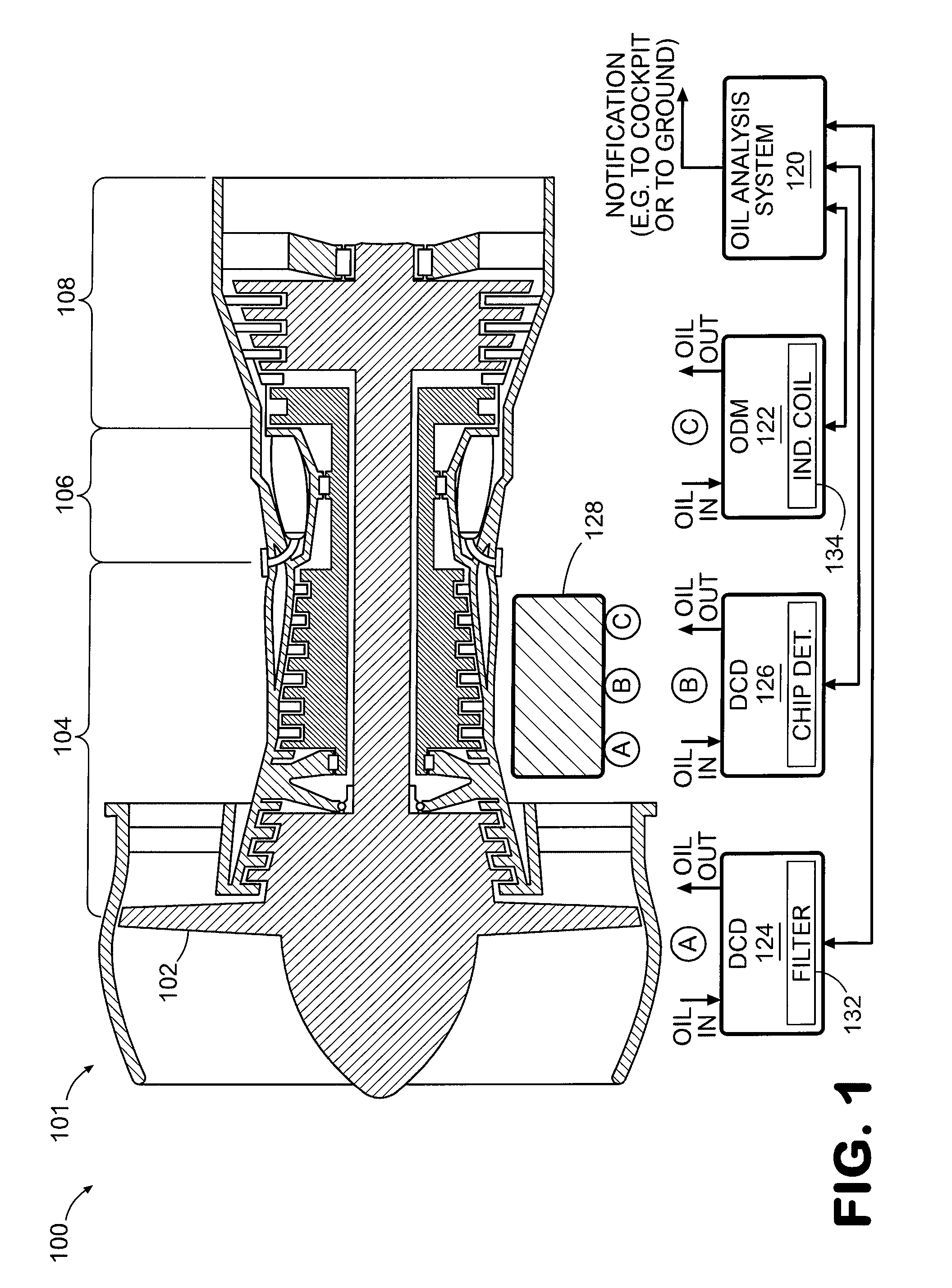
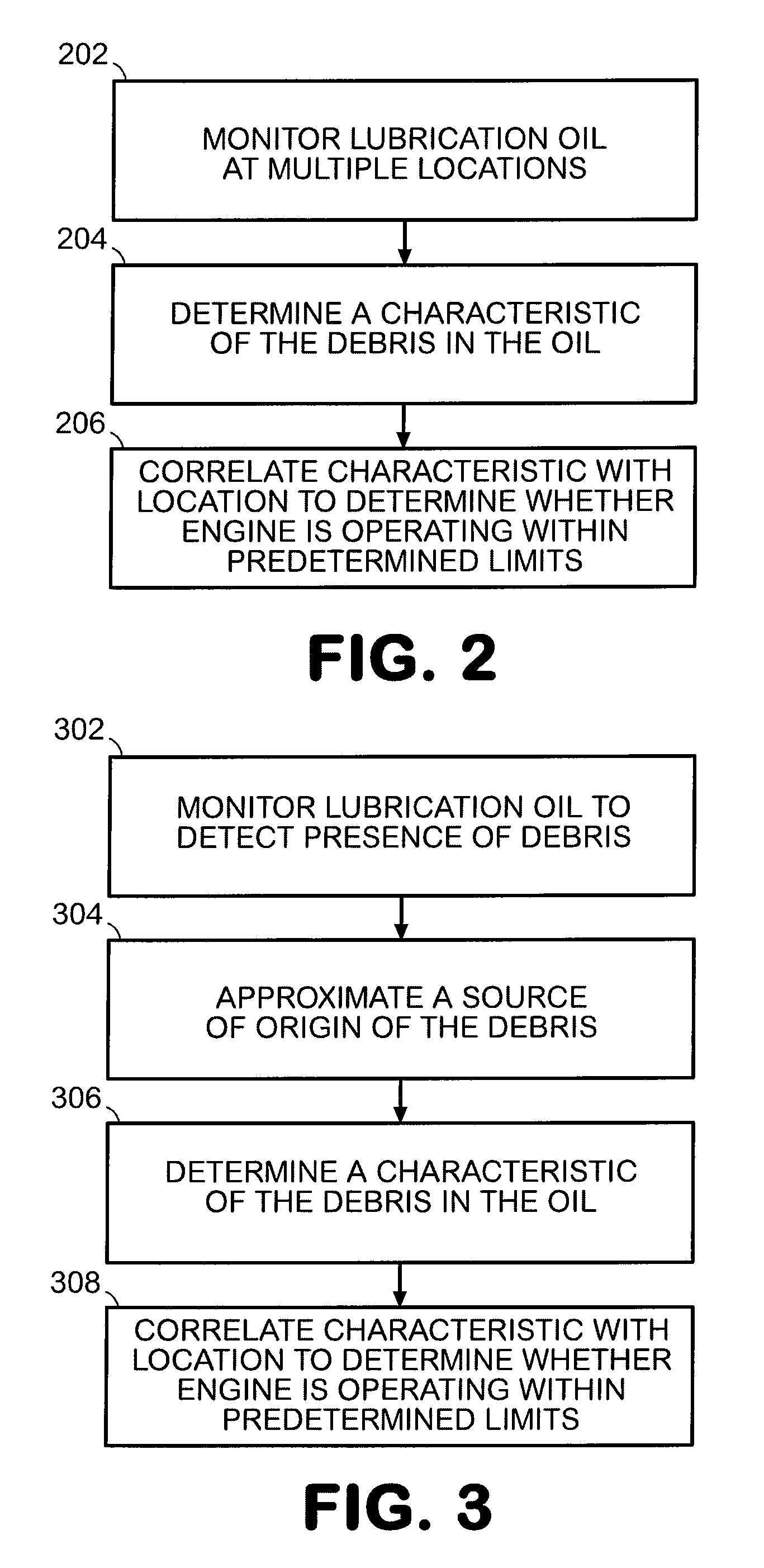
[0016]Systems and methods for monitoring gas turbine engines are provided. In this regard, several exemplary embodiments will be described. In some embodiments, an oil analysis system receives information from various devices, such as one or more debris capture devices and one or more oil debris monitors. Notably, some embodiments can incorporate only one oil debris monitor that is configured to detect the presence of magnetic and nonmagnetic particles in the lubrication oil system of a gas turbine engine. Additionally, the debris capture devices, e.g., magnetic chip detectors, can be located at various locations of the lubrication oil system, thereby assisting in localizing the source of any debris. Information from the debris capture devices and oil debris monitor is analyzed to determine whether or not the engine is operating within predetermined limits. In some embodiments, depending upon the severity of a sensed out-of-limit condition, a notification can be provided to the cock...


PUM

PropertyMeasurementUnit
magneticaaaaaaaaaa
non-magneticaaaaaaaaaa
chemical analysisaaaaaaaaaa

Abstract

Systems and methods for monitoring gas turbine engines are provided. In this regard, a representative method includes: monitoring lubrication oil at multiple locations of the gas turbine engine to detect a presence of debris in the oil; determining a characteristic of the debris in the oil; and correlating the characteristic of the debris with the location of detection to determine, while the gas turbine engine is operating, whether the engine is operating within predetermined limits.

Description

STATEMENT REGARDING FEDERALLY SPONSORED RESEARCH AND DEVELOPMENT[0001]The U.S. Government may have an interest in the subject matter of this disclosure as provided for by the terms of contract number F33615-03-D-23540014 awarded by the United States Air Force.BACKGROUND[0002]1. Technical Field[0003]The disclosure generally relates to gas turbine engine monitoring.[0004]2. Description of the Related Art[0005]Monitoring of lubrication oil of gas turbine engines for debris can be accomplished using a variety of techniques. By way of example, chemical analysis can be used to identify particles of deteriorating mechanical components. However, chemical analysis can be quite time-consuming and typically requires equipment that is used by ground maintenance personnel. Another technique involves the use of an oil filter that is removed from the engine so that captured debris can be analyzed. This technique also is typically performed by ground maintenance personnel.[0006]Another technique in...

Claims


Application Information

Patent Timeline
Patent Type & Authority Patents(United States)
IPC IPC(8): F01D25/18G01L7/00
CPCF01D21/10F01D25/18F02C7/06G01N15/0656G01N33/2858G01N33/2888F05D2260/80F05D2270/11
Inventor SHEVCHENCKO, ERIC ASZOLOMAYER, ROBERT D
Owner RTX CORP
Why Eureka
Try Eureka