Apparatus for transferring particles

a particle and apparatus technology, applied in the direction of catalytic naphtha reforming, chemistry apparatus and processes, naphtha reforming, etc., can solve the problems of physical damage to the particles as well as the equipment, insufficient pneumatic conveying system alone, and sporadic upsets

Inactive Publication Date: 2011-02-15
UOP LLC
View PDF42 Cites 47 Cited by
  • Summary
  • Abstract
  • Description
  • Claims
  • Application Information

AI Technical Summary

Problems solved by technology

Under such conditions, a pneumatic conveying system alone is insufficient to transfer the particles.
Surprisingly, it has been found that a particular unit will operate predominantly in a stable manner but experience sporadic upsets.
These upsets involving a sudden surge of particles from one zone to another, which may reverse the particle flow, have been unpredictable with respect to which unit will be affected, and which particle transfer cycle will experience an upset in an affected unit.
These upsets occur despite conformance to the same design methods.
Such upsets interrupt the consistent flow of particles and can physically damage the particles as well as the equipment.
Although it remains unpredictable whether an upset will occur during any particular cycle in an apparatus, we have discovered that the upsets usually occur during the middle zone depressurization step or the middle zone empty step.

Method used


Image

  • Apparatus for transferring particles
  • Apparatus for transferring particles
  • Apparatus for transferring particles

Examples


Embodiment Construction

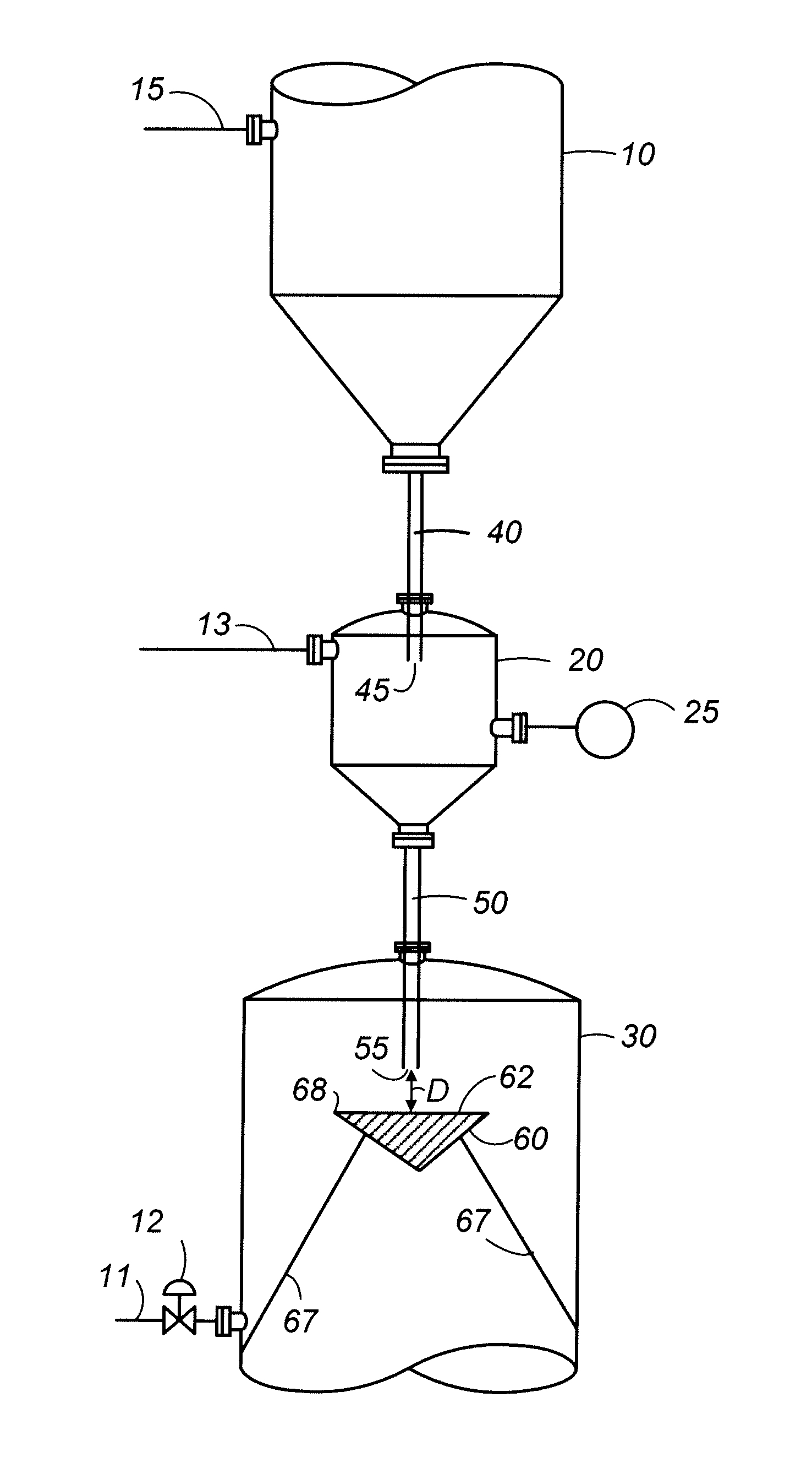
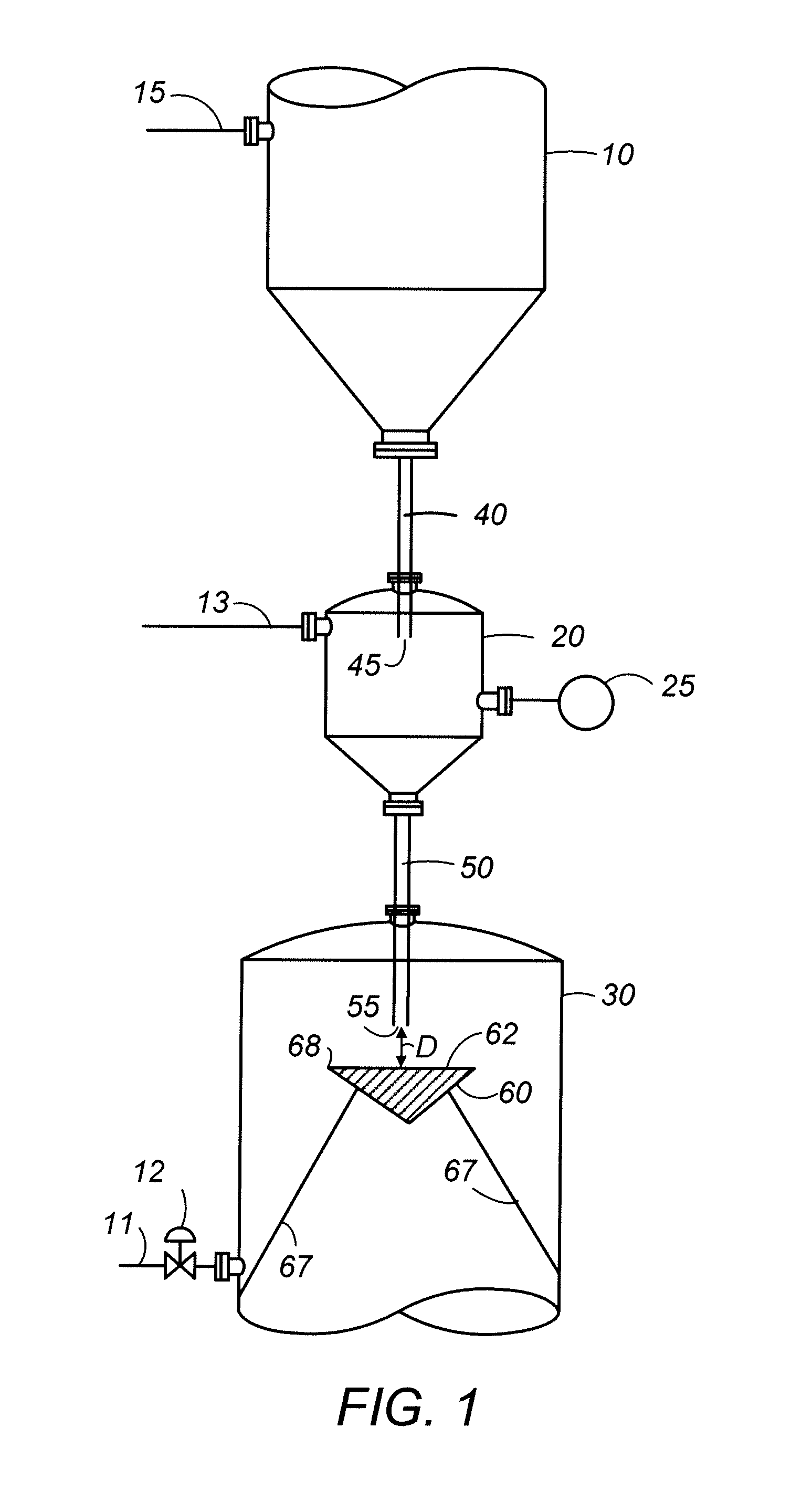
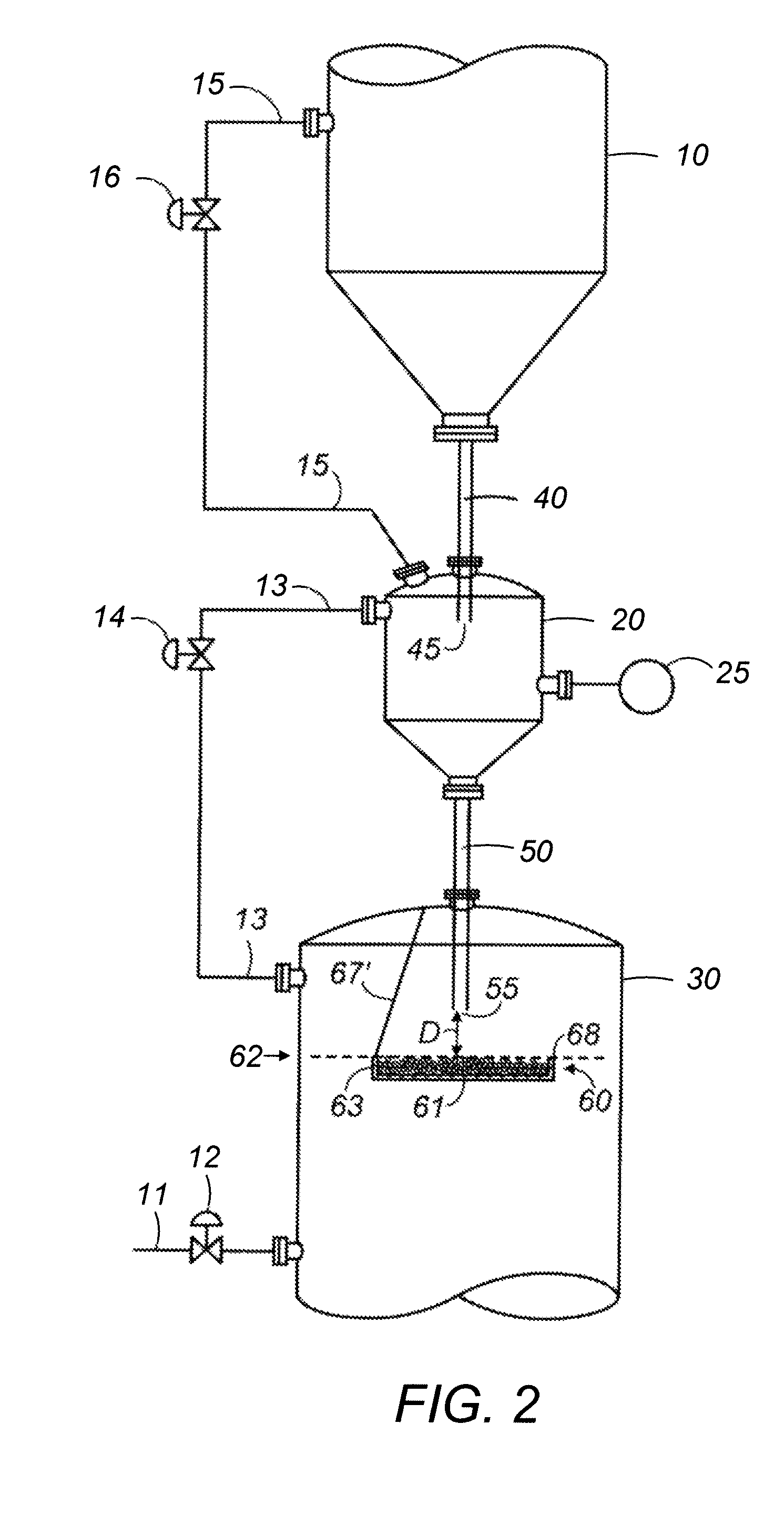
[0020]The invention may be used to transfer solid particulate matter from an upper zone, through a middle zone, to a lower zone where the lower zone pressure is greater than the upper zone pressure. The invention transfers particles without using moving equipment such as valves to block the particle flow path. Generally, particles received in an upper zone are transferred through an upper valveless standpipe or transfer conduit to a middle zone. A lower valveless standpipe or transfer conduit is used to transfer the particles from the middle zone towards an obstruction or body located within a lower zone. Thus the zones, valveless conduits, and obstruction or body may be in particle communication and the valveless conduits may provide particle communication.

[0021]The invention can be used within and / or between a variety of process units to transfer particles, such as catalyst and adsorbents. The upper zone of the invention may receive particles from a separate process zone and the l...


PUM


Abstract

Method and apparatus are provided for transferring particles from an upper zone through an intermediate zone to a lower zone. The transfer of particles between the zones through valveless conduits is regulated by varying the pressure of the intermediate zone and the flow rate of gas passing through the valveless conduits. A body within the lower zone is in particle communication with a valveless conduit and obstructs the particle flow within the lower zone.

Description

FIELD OF THE INVENTION[0001]This invention generally relates to the art of solid particle transport. More specifically, the invention relates to methods and apparatus for transferring particles from an upper zone through a middle zone to a lower zone.BACKGROUND OF THE INVENTION[0002]There are many chemical processes where it is necessary to bring into contact a fluid and a solid particulate matter, such as adsorbents and catalysts. Frequently, chemical reactions as well as physical phenomena occur for a predetermined period of time in the contact zone, e.g. a reaction or adsorption zone. In many of these processes, the particles are transported between two or more particle containing vessels. The particles may be transported for a variety of reasons depending on the process. For example, particles may be transported from one contacting vessel or zone into another contacting zone in order to take advantage of different process conditions to improve product yields and / or purity. In an...

Claims


Application Information

Patent Timeline
Patent Type & Authority Patents(United States)
IPC IPC(8): B65G51/22
CPCB01J8/0025B01J8/003B01J2208/00778
Inventor NAUNHEIMER, CHRISTOPHERSECHRIST, PAUL A.
Owner UOP LLC
Why Eureka
Try Eureka