Housing for an electric appliance

a technology for electric appliances and housing, which is applied in the direction of electrical apparatus casings/cabinets/drawers, domestic cooling apparatus, coupling device connections, etc., can solve the problems of difficult to achieve the required operational safety, the screw connection is subject to a slight load, and the press contact is not sufficient to reliably establish a conductive connection, etc., to achieve the effect of simple, reliable and yet still durable manner

Inactive Publication Date: 2011-02-15
BSH BOSCH & SIEMENS HAUSGERAETE GMBH
View PDF6 Cites 2 Cited by
  • Summary
  • Abstract
  • Description
  • Claims
  • Application Information

AI Technical Summary

Benefits of technology

[0004]The object of the present invention is to specify a housing for an electric appliance in which an electrically conductive connection between two metal parts is formed in a simple, reliable and yet still durable manner.
[0006]The material displacement causes the screw to establish a secure electrical contact to the conductive skin; by simultaneously engaging in the hole in the solid structure it establishes a secure grip there so that the electrical contact between the screw and the conductive skin is not adversely affected by forces which operate on the screw or on the wall. A reliable and durable conductive connection is thus established between the skin and the electrically-conductive support.
[0008]Preferably the recess has a serrated edge since the serrations can be deformed by the screw significantly more easily than an edge which for example runs essentially straight.
[0010]The electrically-conductive skin can be the outer cover of the housing. Since the skin is fastened to the electrically-insulating fixed structure, it does not need to be self-supporting, which means that a thin and low-cost panel can be used for it.

Problems solved by technology

With metal parts which are enameled or coated in some other way to make them electrically insulated such press contact is not sufficient to reliably establish a conductive connection.
It is difficult however to achieve the required operational safety with such a connection, since, to enable the screw to cut the thread, without a disproportionate torque having to be exerted on it, the panel must be quite soft or quite thin, with the result that only a slight load can be imposed on the connection made by the screw.

Method used


Image

  • Housing for an electric appliance
  • Housing for an electric appliance
  • Housing for an electric appliance

Examples


Embodiment Construction

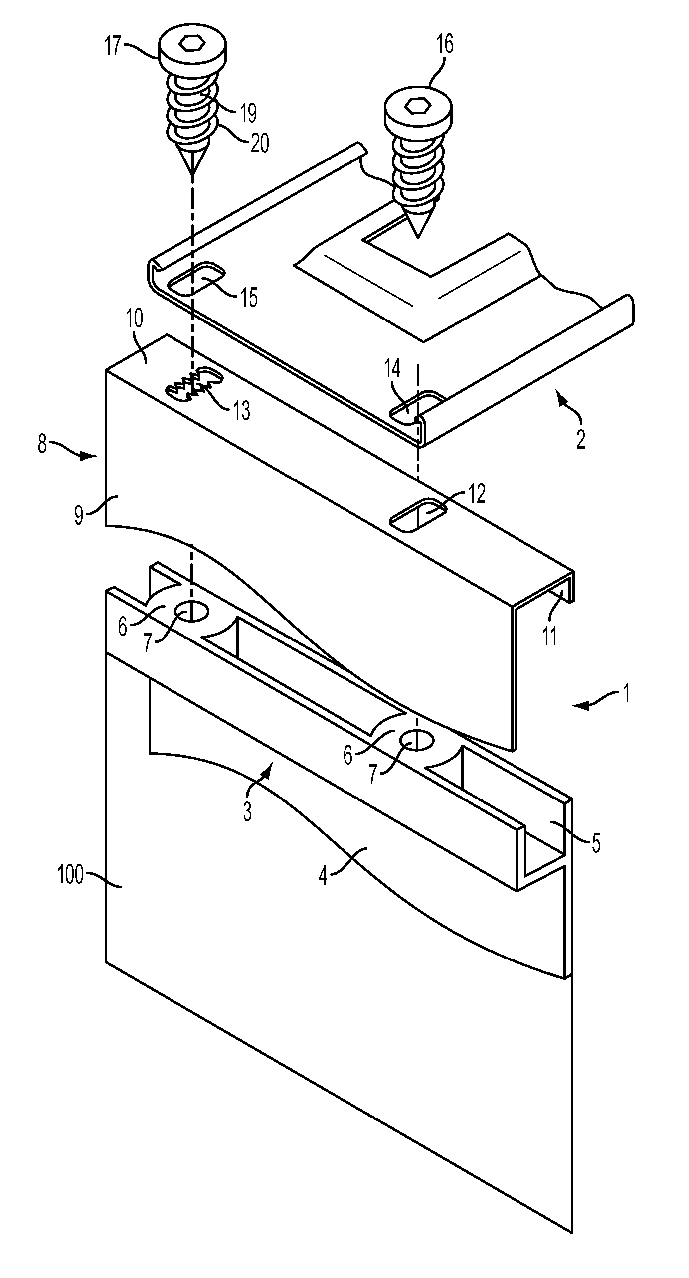
[0018]FIG. 1 shows a perspective exploded view of a housing 100 of a refrigerator including a connection between a housing wall 1 of the refrigerator and a support rail 2 which is provided as a support for a compressor (not shown) of the refrigerator.

[0019]The housing wall 1 shown in section comprises an inner part 3 made of plastic and an outer part 8 formed from enameled metal. The inner part 3 comprises a plate 4, which forms an inner side of the housing wall and at the free edge of which a U-profile 5 is formed. Molded into the groove of the U profile 5 in the perspective view shown in FIG. 1 are a number of massive plastic blocks 6 which join the opposite legs of the U profile 5 to each other and in which a pocket hole 7 is formed in each case.

[0020]The outer part 8 of the housing wall 1 comprises a plate 9 running in parallel to wall plate 4 of the inner part 3 as well as a first bar 10 bent at right angles and a second bar 11 angled from the edge of the first bar 10 in parall...


PUM


Abstract

A housing for an electric appliance includes a wall with an electrically insulating solid structure, an electrically conductive skin that is fastened to the solid structure, an electrically conductive support, and at least one screw that engages into a bore of the structure and keeps the support pressed against the wall. The screw extends through a recess of the electrically conductive skin. Material of the electrically conductive skin that surrounds the recess is displaced by the screw.

Description

BACKGROUND OF THE INVENTION[0001]The present invention relates to a housing for an electric appliance and especially to the grounding of components of this housing. To ensure that electrical appliances can be operated safely, metal parts which can be touched by a user and which conduct voltage while the appliance is operating or for which there is the possibility of them being able to conduct a voltage as a result of a fault, must be grounded. For blank metal parts this can be done by pressing the parts, e.g. screwing them firmly onto a grounding conductor. Such a grounding conductor can for example be a wire connected to ground potential of an ac mains power socket or any electrically-conductive part of the housing which is connected directly or indirectly electrically-conductively to such a wire.[0002]With metal parts which are enameled or coated in some other way to make them electrically insulated such press contact is not sufficient to reliably establish a conductive connection...

Claims


Application Information

Patent Timeline
Patent Type & Authority Patents(United States)
IPC IPC(8): H02G3/08F16B1/00F16B5/02F16B25/00F25D23/00H05K5/02
CPCF16B5/02F25D23/006F16B25/00F16B2001/0064Y10S248/906F16B2200/93
Inventor GUTTINGER, MARC
Owner BSH BOSCH & SIEMENS HAUSGERAETE GMBH
Why Eureka
Try Eureka