
Image forming apparatus and recording medium on which interrupt control program is recorded

a technology of image forming apparatus and recording medium, which is applied in the direction of electrographic process apparatus, instruments, optics, etc., can solve the problems of insufficient device to maintain the fixing temperature, the start-up time delay, and the decrease in fixing performance, so as to suppress the reduction of job efficiency and improve fixability

Inactive Publication Date: 2011-02-15
SHARP KK
View PDF9 Cites 2 Cited by
  • Summary
  • Abstract
  • Description
  • Claims
  • Application Information

AI Technical Summary

Benefits of technology

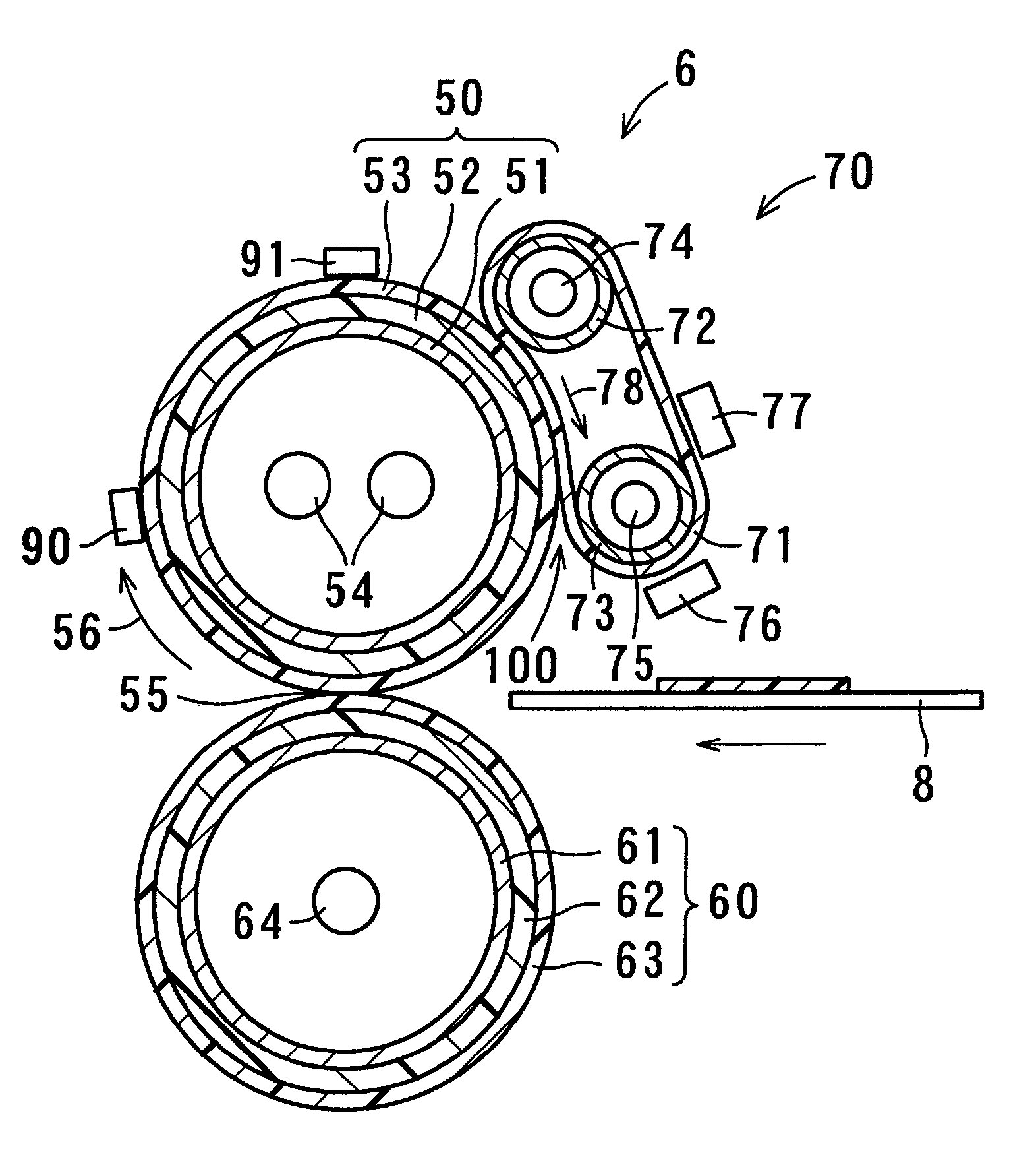
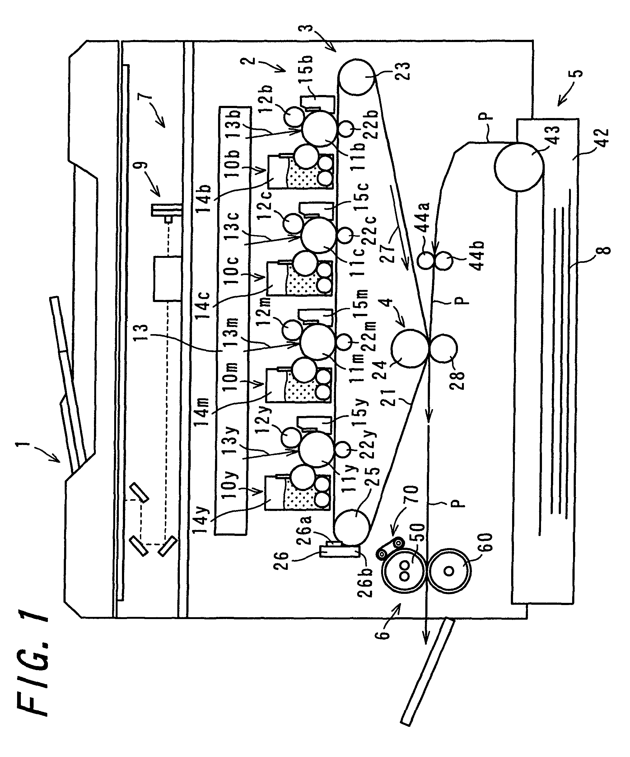
The invention provides an image forming apparatus with a fixing device that can improve fixability and suppress a decrease in job efficiency after startup. The apparatus includes a toner image forming section, transfer section, fixing device, and interrupt control section. The external heating section heats the fixing member from the exterior, and the fixing member temperature detection section detects the surface temperature of the fixing member. The interrupt control section carries out an interrupt control so as to interrupt the job printing when the surface temperature of the fixing member decreases to a job interrupt reference temperature. By setting at least two levels as the job interrupt reference temperature and selecting the appropriate level for either or both of a job immediately after startup or a job after a sleep mode, the apparatus can achieve a balance between ensuring fixability and job efficiency.

Problems solved by technology

However, this kind of adaptation causes increasing the heat capacity of the fixing roller and, in the event that this kind of fixing roller with a high heat capacity is heated only by a heating source included therein, problems occur, such as a start-up time delay, or a decrease in fixing performance due to a decrease in temperature followability of the fixing roller at a continuous output time.
As the temperature distribution from the interior to surface of the fixing roller immediately after the start-up, and that in the standby condition, tend to be totally opposite to each other in this way, in the event of carrying out a continuous output immediately after the start-up, the fixing roller surface is rapidly deprived of heat by paper, making only a supply of heat from the external heating device insufficient to maintain the fixing temperature, and there is a fear that the fixability decreases.
However, with the image forming apparatus disclosed in JP-A 2005-202359, as the job interrupt reference temperature is uniformly determined without distinguishing between being immediately after the start-up and in the standby condition, there being a problem with a decrease in job efficiency and the fixability immediately after the start-up, a poor fixing or the decrease in job efficiency occurs when printing the job immediately after the start-up.

Method used


Image

  • Image forming apparatus and recording medium on which interrupt control program is recorded
  • Image forming apparatus and recording medium on which interrupt control program is recorded
  • Image forming apparatus and recording medium on which interrupt control program is recorded

Examples


reference example 1

[0146]As the fixing roller, a roller of approximately 40.0 mm in outer diameter is used wherein a 2.5-mm silicone rubber layer is formed on an aluminum metal core of 35 mm in outer diameter and 2 mm in wall thickness, and furthermore, a 40-μm PFA tube layer is provided thereon. As the pressure roller, a roller of approximately 40.0 mm in outer diameter is used wherein a 2.5 mm-silicone rubber layer is formed on an aluminum metal core of 35 mm in outer diameter and 2 mm in wall thickness, and furthermore, a 40-μm PFA tube layer is provided thereon. As the heating belt, an endless belt is used wherein a 90-μm thick polyimide base material formed in a 31 mm diameter cylindrical shape is coated with a PTFE layer of approximately 20 μm.

[0147]Aluminum rollers of 2 mm in wall thickness and 16 mm in outer diameter are used as the first pressing roller and second pressing roller. Also, 700W halogen lamps are provided inside the fixing roller, a 500W halogen lamp inside each of the first pres...

reference example 2

[0148]The job printing is carried out in the same way as in Reference Example 1, except that the job interrupt reference temperature is changed from 155° C. to 170° C.

[0149]The fixability of Reference Example 1 and Reference Example 2 is evaluated using a bending test such that an image after being fixed (a portion corresponding to the black solid image in the previously described chart) is bent under a certain load condition, and subsequently rubbed under a certain load condition, and the width of a portion of the image removed by the rubbing (hereinafter described also as a “removed width”) and the removed width of a limit sample are compared. A cylindrical 1 kg-brass weight is used in order to give a certain load. In the test, the narrower the removed width becomes, the better the fixability, and the wider the removed width becomes, the worse the fixability, and therefore the fixability is superior to that of the limit sample in the event that the removed width is narrower than t...


PUM


Abstract

An image forming apparatus is provided having a fixing device which heats a fixing roller from the surface thereof by means of an external heating device, which image forming apparatus is capable of improving fixability immediately just after a start-up and enhancing a job efficiency. An image forming apparatus includes a toner image forming section, a transfer section, a fixing device, and an interrupt control section. At least two levels are set as a job interrupt reference temperature, the interrupt control section individually selects, from among the at least two levels of job interrupt reference temperature, the level to be used for either or both of a job immediately after the start-up from a power-on and a job immediately after a return from a sleep mode, and the level(s) for other job(s), and carries out an interrupt control using the selected level of job interrupt reference temperature.

Description

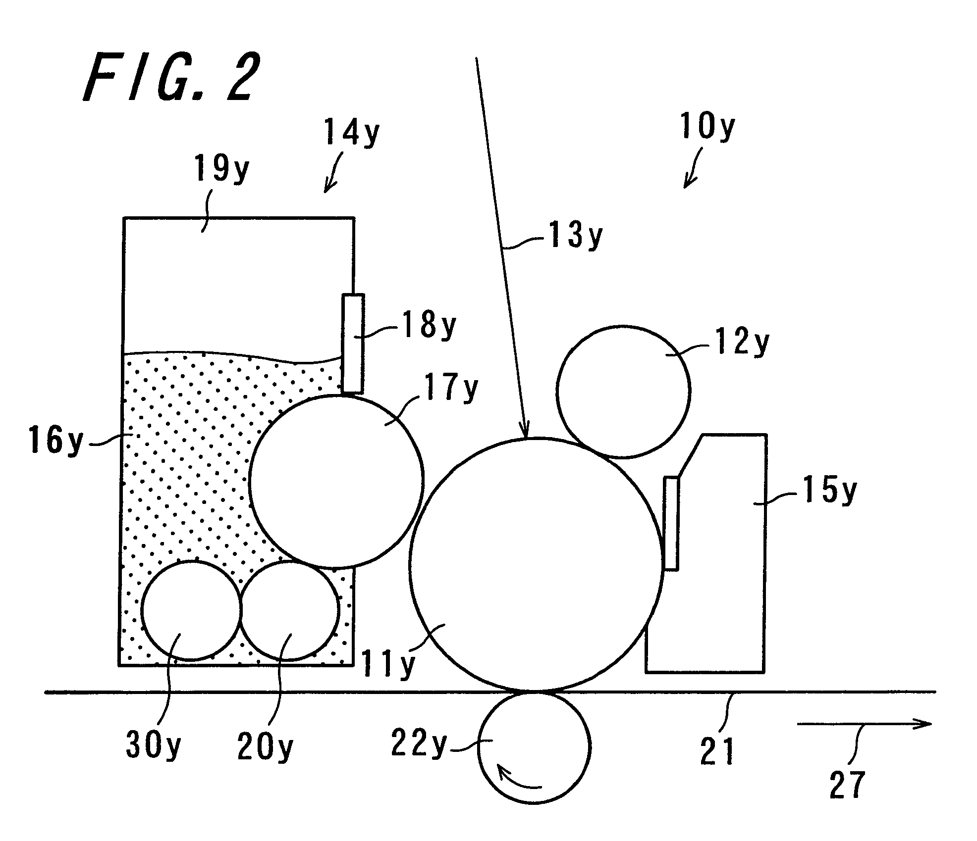
CROSS-REFERENCE TO RELATED APPLICATION[0001]This application claims priority to Japanese Patent Application No. 2008-217227, which was filed on Aug. 26, 2008, the contents of which are incorporated herein by reference in their entirety.BACKGROUND OF THE INVENTION[0002]1. Field of the Invention[0003]The present invention relates to an image forming apparatus and a recording medium on which an interrupt control program is recorded.[0004]2. Description of the Related Art[0005]An electrophotographic image forming apparatus is capable of forming a high-quality image with favorable reproducibility and operability at low cost. This is why the electrophotographic image forming apparatus has been widely used in a copier, a printer, a facsimile machine, a multifunction machine having two or more of these functions just stated, and the like machine. The electrophotographic image forming apparatus includes, for example, a photoreceptor, a charging device, an exposing device, a developing device...

Claims


Application Information

Patent Timeline
Patent Type & Authority Patents(United States)
IPC IPC(8): G03G15/20
CPCG03G15/2039
Inventor YAMAJI, HIROYUKI
Owner SHARP KK
Learn More