
System and method for providing head end power for use in passenger train sets

a passenger train and head end technology, applied in the field of railway train sets, can solve the problems of separate system, high noise and harmful emissions, and less horsepower available for accelerating

Active Publication Date: 2011-02-22
BACHMAN ERIC C
View PDF20 Cites 7 Cited by
  • Summary
  • Abstract
  • Description
  • Claims
  • Application Information

AI Technical Summary

Problems solved by technology

A passenger train's travel through these areas is accompanied by high levels of noise and harmful emissions, which is undesirable both for the train's passengers and residents of the area.
However, unlike freight railcars, passenger railcars require electrical power for various housekeeping applications unrelated to locomotion, such as heating, cooling, ambient lighting, and energizing electrical outlets.
For instance, because the parasitic generator obtains its energy from the main diesel engine, less horsepower is available for accelerating the train and / or the engine has to maintain higher power output and fuel consumption to sustain the desired cruising speed.
While a separate engine / generator set dedicated to non-propulsion purposes would not rob energy from the primary power generator, the use of a separate system translates into higher maintenance costs for the passenger train.
In addition, both types of HEP systems produce undesirable levels of high-pitched noise as they utilize generators that run at high RPMs.
This noise is particularly bothersome in passenger trains as it affects the comfort of the passengers, bystanders, and residents.
Also, both types of systems require the consumption of additional fuel, which again translates into higher costs, as well as increased emission levels.
In other words, the excess energy is wasted.
However, as freight trains do not make frequent stops, dynamic braking in freight applications does not provide enough excess energy for an application where the demand for the energy is continuous.

Method used


Image

  • System and method for providing head end power for use in passenger train sets
  • System and method for providing head end power for use in passenger train sets
  • System and method for providing head end power for use in passenger train sets

Examples


Embodiment Construction

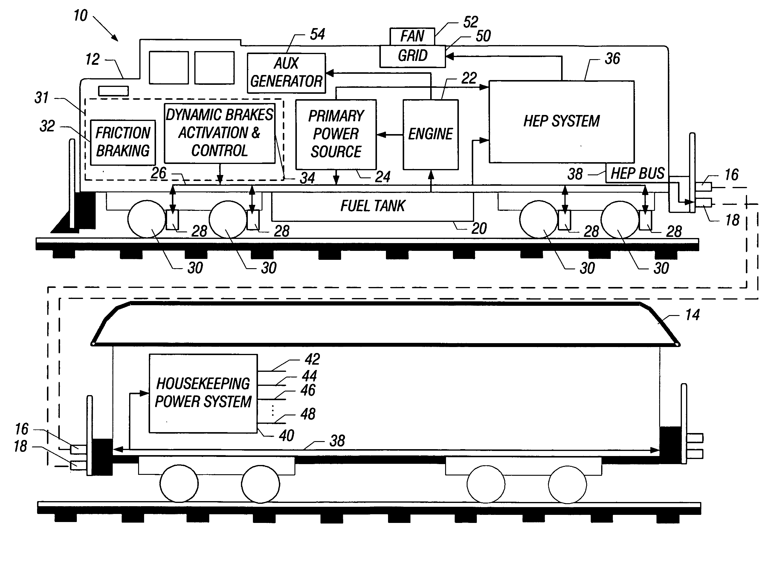
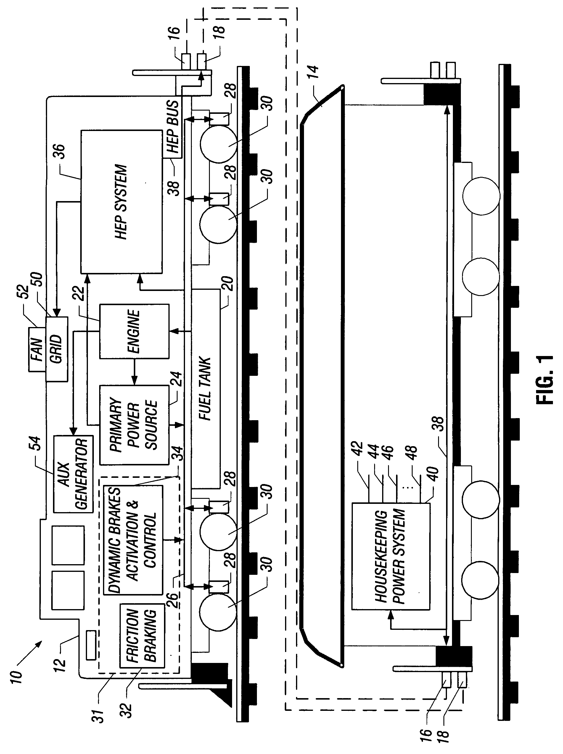
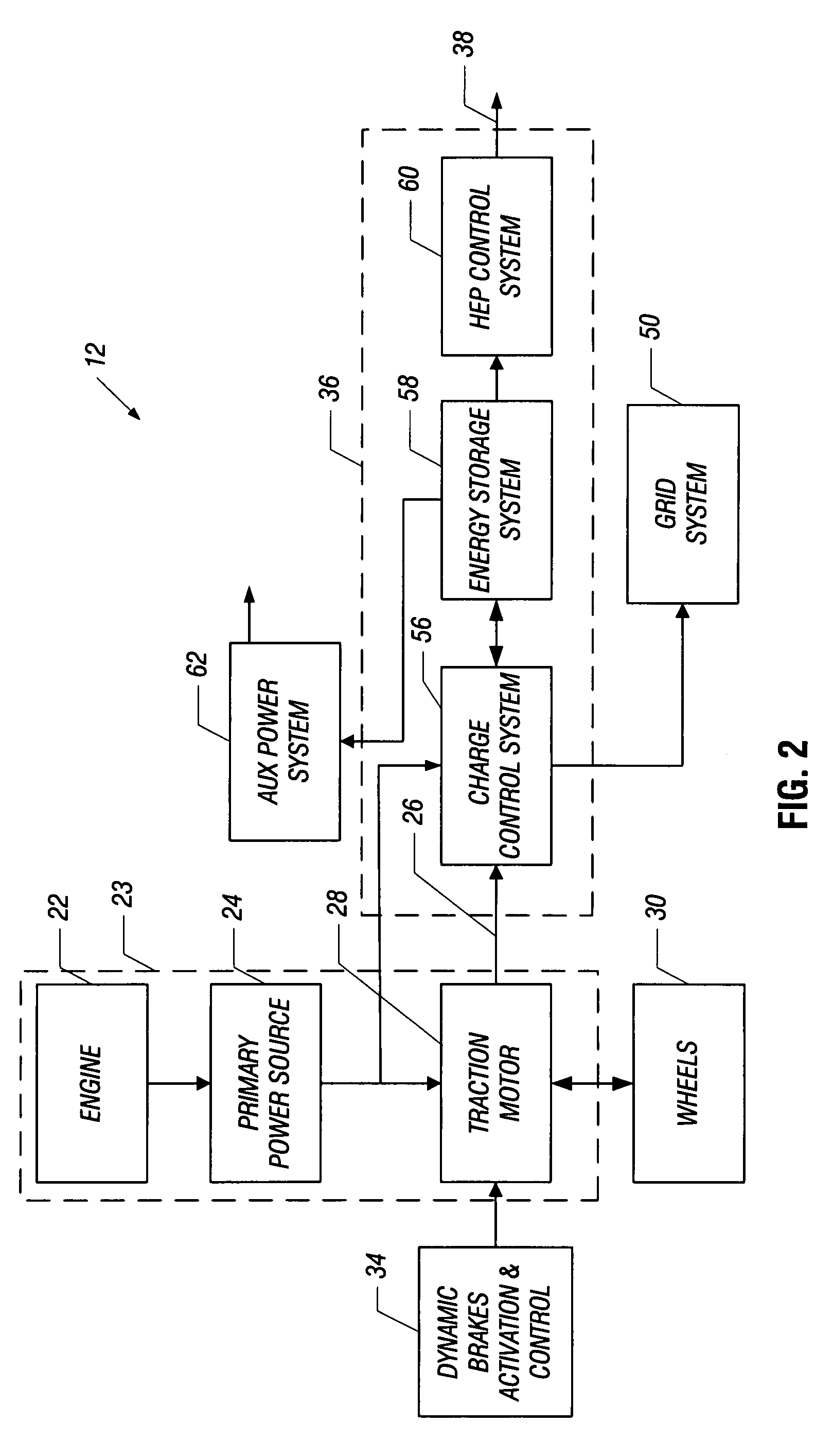
FIG. 1 shows an exemplary embodiment of a passenger train set 10 that includes a diesel locomotive 12 and at least one passenger railcar 14. Railcar 14 is mechanically and electrically coupled to locomotive 12 via coupling connections 16 and 18, respectively. In general, locomotive 12 carries a propulsion system 23 (see FIG. 2) that includes a main engine 22, a primary power source 24, a traction bus 26, and a plurality of traction motors 28. Locomotive 12 also carries a fuel tank 20 that provides fuel to the primary engine 22.

The primary power source 24 provides primary power in the appropriate form required by the particular traction bus 26 and may include, for example, a generator, an alternator, etc. Propulsion system 23 is operable in a motoring mode in which train set 10 is moved or accelerated on a track and in a dynamic braking mode in which train set 10 is slowed or brought to a stop. In the motoring mode, main engine 22 drives primary power source 24 which then produces pr...


PUM


Abstract

A head end power system carried on a locomotive for a passenger train set that captures and stores excess electrical energy generated during dynamic braking of the locomotive. This excess electrical energy is converted to head end power for use on attached passenger railcars. Because passenger trains activate dynamic braking frequently, sufficient dynamic braking energy can be captured to supply a substantially continuous demand for head end power. In the event that the amount of captured energy is insufficient to meet demand, the head end power system may supplement the captured energy with energy generated by the primary power source on the locomotive.

Description

This application claims the benefit of co-pending U.S. Provisional Application Ser. No. 60 / 779,995 entitled, “LOCOMOTIVE HYBRID HEAD END POWER UNIT FOR PASSENGER TRAIN SETS,” filed on Mar. 7, 2006, which is incorporated herein by reference in its entirety.BACKGROUNDThe present invention relates generally to railway train sets, and more particularly, to a system and method for generating head end power for use in passenger train sets.In many regions of the world, particularly in large cities, passenger rail is a widely used mode of transportation. In these regions, people often use passenger trains to commute to the workplace from suburbs or smaller towns outside the city. The passenger train makes frequent stops and passes through residential areas as well as travels in congested urban areas. A passenger train's travel through these areas is accompanied by high levels of noise and harmful emissions, which is undesirable both for the train's passengers and residents of the area.Both ...

Claims


Application Information

Patent Timeline
IPC IPC(8): B61C3/00
CPCB60L1/003B60L1/14B60L7/04B60L7/12B60L7/22B60L7/26B60L11/005B60L11/123B60L11/1861B60L1/02Y02T10/6217B60L2260/28B60L2200/26Y02T10/7044Y02T10/7005Y02T10/705Y02T10/7022B60L50/40B60L50/61Y02T10/62Y02T10/70
Inventor BACHMAN, ERIC C.
Owner BACHMAN ERIC C
Learn More