
Nozzle cleaning apparatus, nozzle cleaning method, and a computer-readable storage medium storing nozzle cleaning program

a technology of nozzles and cleaning methods, which is applied in the direction of cleaning machines, carpet cleaners, cleaning with liquids, etc., can solve the problems that the above method cannot remove adhering matter that has already been crystallized, the processing of substrates is adversely affected, and the dew drops are likely to form on the outer circumferential surface of the nozzles, so as to reduce the cost of cleaning, prevent any trouble in the processing of substrates, and efficient cleaning

Active Publication Date: 2011-02-22
TOKYO ELECTRON LTD
View PDF5 Cites 7 Cited by
  • Summary
  • Abstract
  • Description
  • Claims
  • Application Information

AI Technical Summary

Benefits of technology

The present invention provides a nozzle cleaning technique that can efficiently clean a nozzle for discharging a process liquid to a substrate, preventing any troubles in the processing of the substrate and reducing the cost related to cleaning. The cleaning apparatus includes a cleaning liquid supply unit, a cleaning container with an inner surface of a funnel-like shape, and a cleaning liquid supply path connected to the cleaning liquid supply unit. The cleaning liquid is supplied along the inner surface of the cleaning container, creating a vortex of the solvent whirling around the nozzle. The cleaning method involves accommodating the nozzle in the cleaning container and supplying the solvent to the cleaning chamber, creating a solvent atmosphere in the cleaning chamber. The computer-readable storage medium stores a nozzle cleaning program for controlling the nozzle cleaning apparatus or the substrate processing system.

Problems solved by technology

However, when a nozzle is placed in a solvent vapor atmosphere of a high concentration, dew drops are likely to be formed on the outer circumferential surface of the nozzle.
If the dew drops fall on a substrate, processing of the substrate may be adversely affected.
In addition, adhering matters that have already been crystallized cannot be removed by the above method.
Thus, it is necessary to make the nozzle cleaning apparatus with high precision, which results in an increased apparatus cost.

Method used


Image

  • Nozzle cleaning apparatus, nozzle cleaning method, and a computer-readable storage medium storing nozzle cleaning program
  • Nozzle cleaning apparatus, nozzle cleaning method, and a computer-readable storage medium storing nozzle cleaning program
  • Nozzle cleaning apparatus, nozzle cleaning method, and a computer-readable storage medium storing nozzle cleaning program

Examples


Embodiment Construction

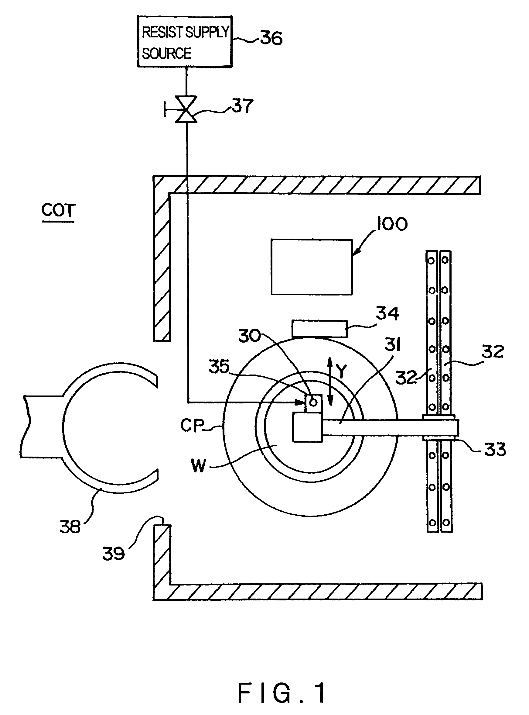
[0023]Preferred embodiments of a nozzle cleaning apparatus and a nozzle cleaning method according to the present invention will be described below with reference to the accompanying drawings. At first, the overall structure of a resist coating system COT incorporating the nozzle cleaning apparatus in one embodiment of the present invention is described with reference to FIG. 1.

[0024]An annular cup CP is arranged on a bottom central portion in the resist coating system COT. A spin chuck (which is invisible because the spin chuck is positioned below a wafer W) is disposed inside the cup CP. The spin chuck is driven for rotation by a motor (not shown), while the wafer W is being held on the spin chuck by vacuum chucking.

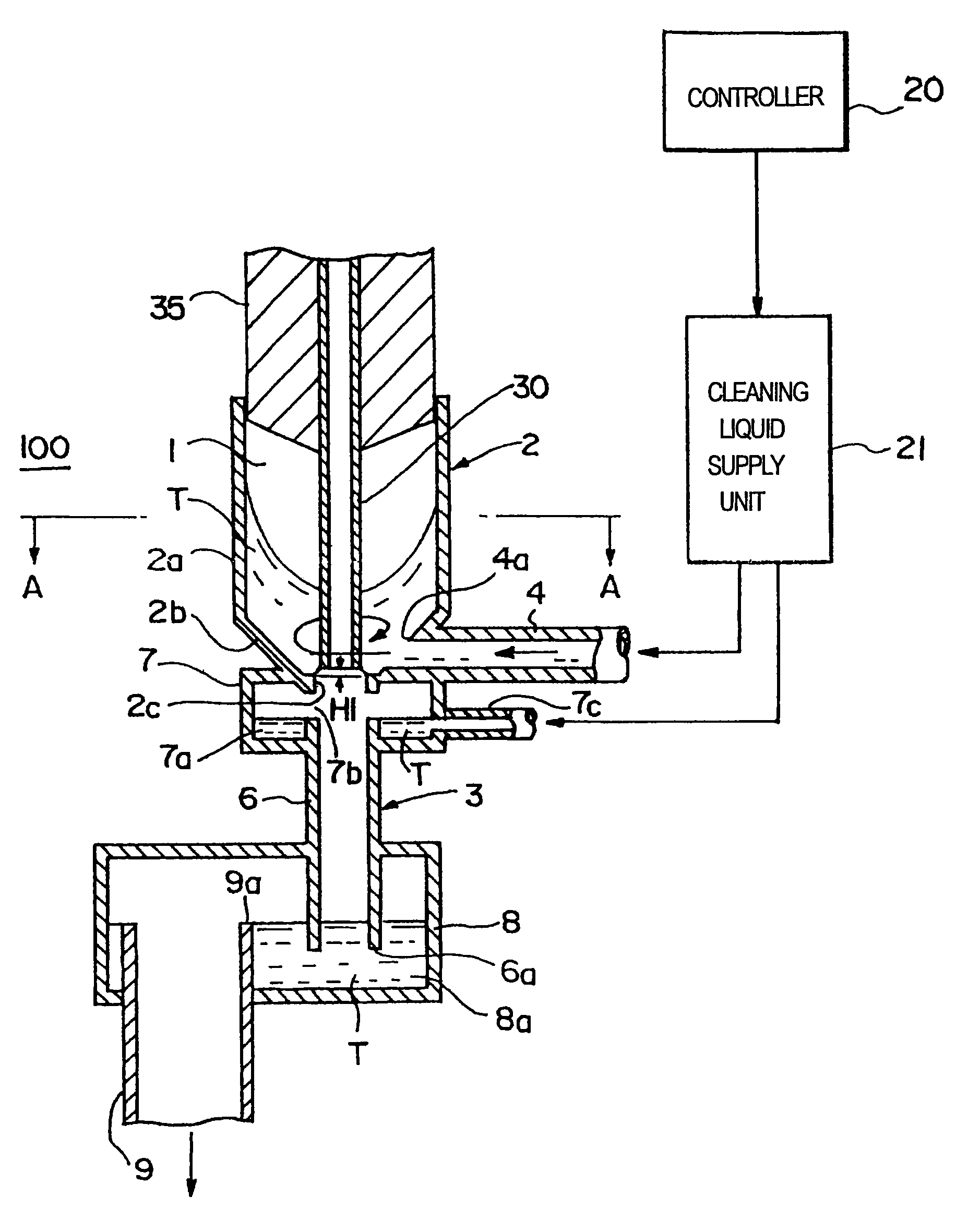
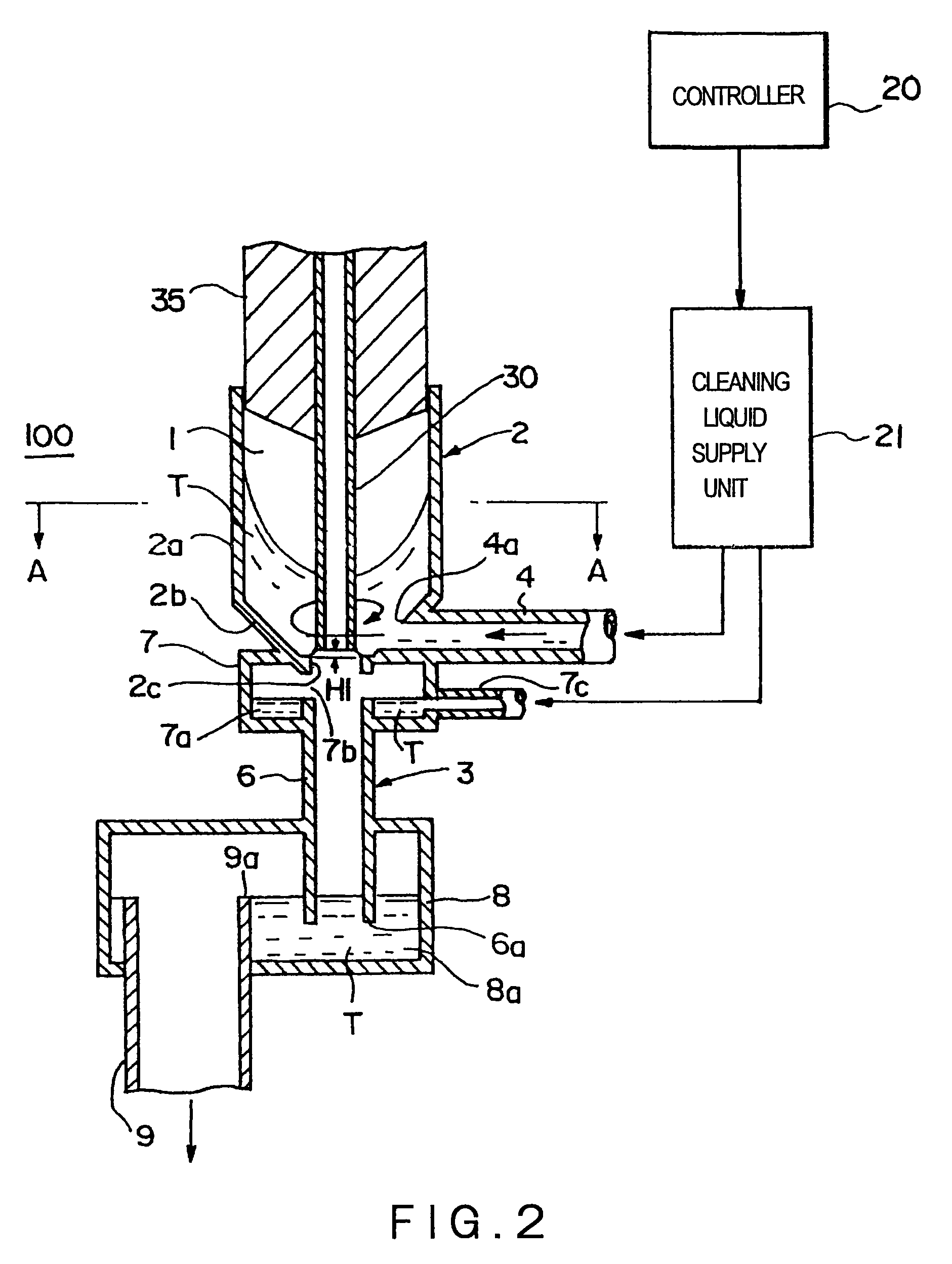
[0025]A photoresist is supplied from a resist supply source 36, through a pipe in which a valve 37 is disposed, into a resist supply nozzle 30 (hereinafter referred to simply as “nozzle 30”), and the photoresist is discharged from a discharge port formed in the tip of t...


PUM


Abstract

Disclosed are a nozzle cleaning apparatus and a nozzle cleaning method, which are capable of effectively cleaning a nozzle for discharging a process liquid to a substrate, with a simple structure and a low cost. A nozzle 30 is accommodated in a cleaning container 2 having a funnel-shaped portion 2b. A solvent T as a cleaning liquid is supplied along an inner surface of the funnel-shaped portion 2b. The solvent T forms a vortex flow whirling around the nozzle 30. By exposing the nozzle 30 to the vortex flow, the nozzle 30 can be effectively, thoroughly cleaned.

Description

TECHNICAL FIELD[0001]The present invention relates to a technique for cleaning a nozzle for discharging a process liquid, such as a photoresist, to a substrate.BACKGROUND ART[0002]In semiconductor device manufacturing, a desired circuit pattern is formed by photolithography that applies a photoresist liquid to a substrate having a predetermined film formed thereon to form a resist film, exposes the resist film with the desired circuit pattern and develops it. More particularly, a wafer as a substrate is subjected to a series of processes including a cleaning process, a dehydration baking process, an adhesion (hydrophobizing) process, a resist coating process, a pre-baking process, an exposure process, a developing process, and a post-baking process.[0003]In a resist coating system that forms a resist film by supplying a photoresist liquid (hereinafter referred simply as “resist”) to a wafer, it sometimes occurs that, a resist adhering to the tip of the resist supplying nozzle after ...

Claims


Application Information

Patent Timeline
Patent Type & Authority Patents(United States)
IPC IPC(8): B08B3/04
CPCB05B15/025B05B15/0266H01L21/67051B05B15/0258B05B15/55B05B15/555B05B15/557B05C5/00
Inventor HIRAO, TAKESHIFUJIMOTO, AKIHIROSOUMA, YASUTAKA
Owner TOKYO ELECTRON LTD
Features
  • Generate Ideas
  • Intellectual Property
  • Life Sciences
  • Materials
  • Tech Scout
  • Unparalleled Data Quality
  • Higher Quality Content
  • 60% Fewer Hallucinations
Learn More