Riserless modular subsea well intervention, method and apparatus

a modular, subsea well technology, applied in the direction of sealing/packing, underwater equipment, borehole/well accessories, etc., can solve the problems of large vessel, specialized vessel, bop/lubricator package, vessel cannot hold position,

Inactive Publication Date: 2011-02-22
SAIPEM AMERICA
View PDF50 Cites 29 Cited by
  • Summary
  • Abstract
  • Description
  • Claims
  • Application Information

AI Technical Summary

Problems solved by technology

The main disadvantage of this method is the large, specialized vessel that is required to deploy the workover string and the workover string needed to deploy the BOP.
A common problem with both the workover string method and the BOP / lubricator package method is encountered during a “drive-off” condition.
A drive-off condition occurs when by accident or design the surface vessel is forced to move away from its position over the well without first recovering the equipment attached to the tree.
If for any reason, there is a failure in the computer, the thrusters, or any related equipment, the vessel will not be able to hold position or it may be driven off position by incorrect action of the thrusters.

Method used


Image

  • Riserless modular subsea well intervention, method and apparatus
  • Riserless modular subsea well intervention, method and apparatus
  • Riserless modular subsea well intervention, method and apparatus

Examples


Embodiment Construction

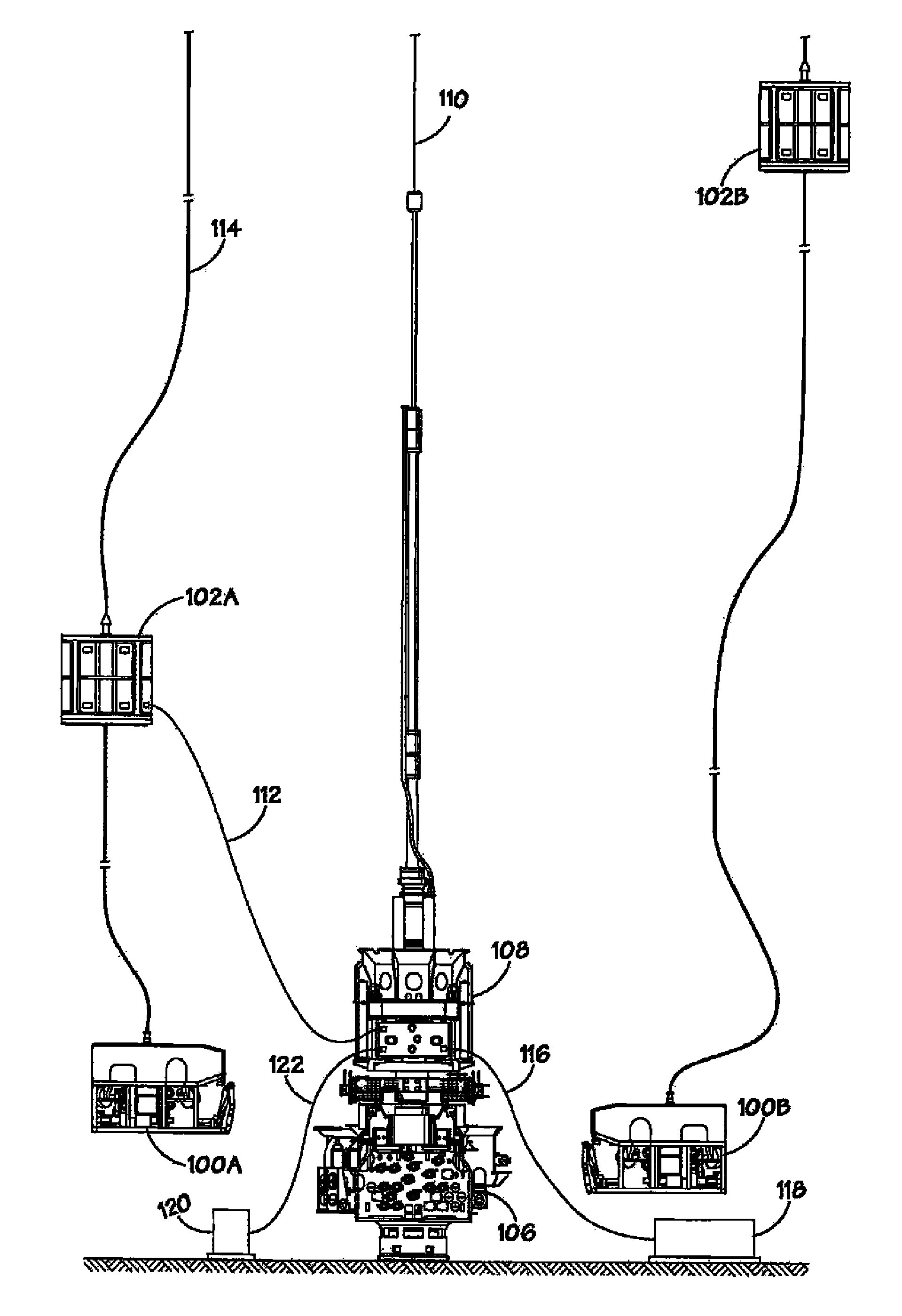
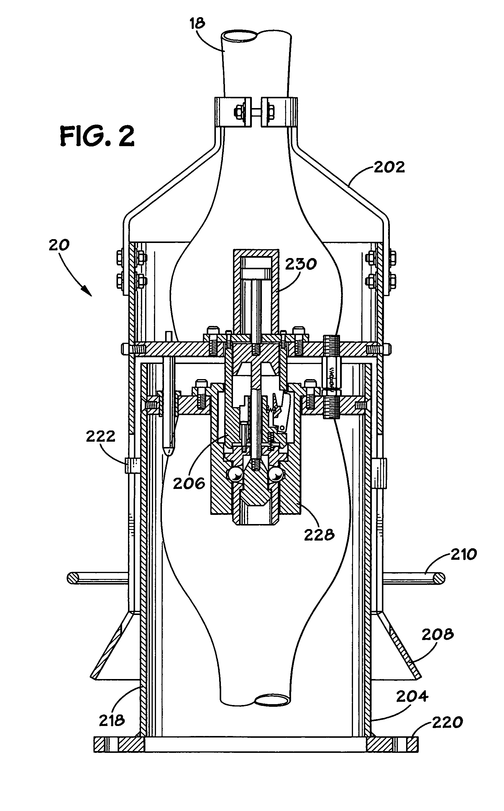
[0022]The method and apparatus described herein allows modular installation of a riserless subsea well intervention equipment and eliminates the need to recover the equipment in a drive-off condition. Dynamic disconnection from the tree-mounted equipment is accomplished by a special, fail-safe disconnect assembly, half of which is fitted to the subsea end of the umbilical and the other half being mounted to the lower end of the lubricator assembly. The system described herein has the further advantage of operation with a smaller vessel than prior art systems because of the smaller and less specialized surface handling equipment used by the present invention (hydraulic reservoir skid, hydraulic accumulator, hydraulic power unit, and hydraulic umbilical reel). Furthermore, leaving the subsea equipment secured to the tree during a drive-off condition reduces the disconnect time and provides less risk of damage to the tree or the environment.

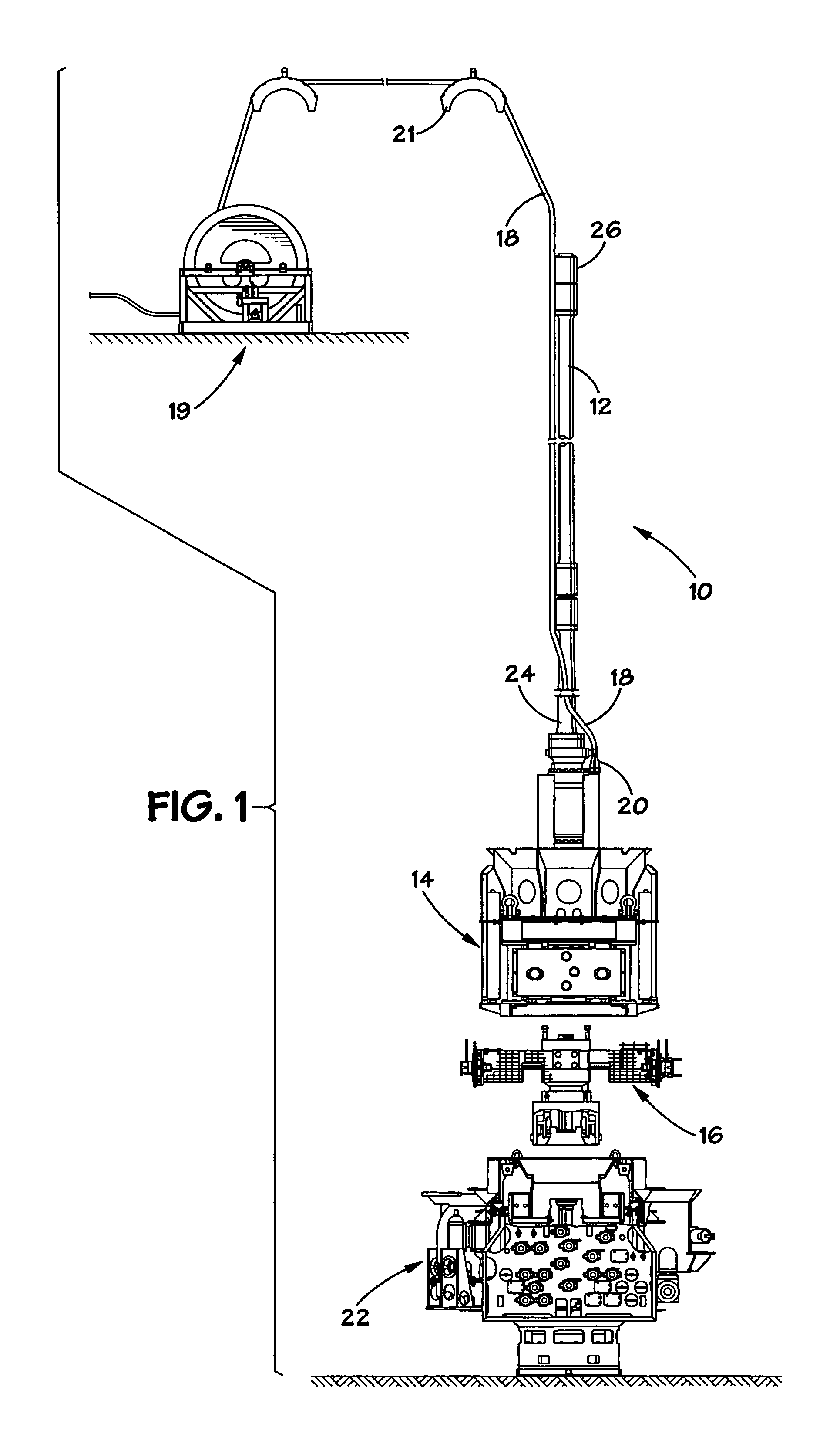
[0023]Referring to FIG. 1, a preferred embodi...


PUM


Abstract

A subsea well intervention system that permits dynamic disconnection from subsea well intervention equipment without removing any of the equipment during a drive-off condition is provided. The system includes a blowout preventer module operatively connected to a subsea tree and a subsea control system. The subsea control system is connected via electrical jumper to an ROV's tether management system. The subsea control system is connected via hydraulic jumpers to a multipurpose fluid-injection skid and one or more hydraulic accumulation banks. A fail-safe disconnect assembly is utilized with respect to the electrical jumper in order to provide easy removal during a drive-off condition.

Description

PRIORITY CLAIM[0001]This application is a continuation-in-part application claiming priority to U.S. patent application Ser. No. 11 / 078,119, filed Mar. 11, 2005, which is incorporated herein by reference.BACKGROUND OF THE INVENTION[0002]The present invention relates generally to a subsea well intervention system, and more specifically to a riserless modular subsea well intervention system.[0003]Oil and gas wells frequently require subsurface maintenance and remediation to maintain adequate flow or production. This activity is commonly referred to as “workover.” During the workover specialized tools are lowered into the well by means of a wire line and winch. This wire line winch is typically positioned on the surface and the workover tool is lowered into the well through a lubricator and blowout preventer (BOP). Workover operations on subsea wells require specialized intervention equipment to pass through the water column and to gain access to the well. The system of valves on the w...

Claims


Application Information

Patent Timeline
Patent Type & Authority Patents(United States)
IPC IPC(8): E21B29/12E21B7/12
CPCE21B7/124E21B19/002E21B33/076E21B33/038E21B33/035E21B33/0355
Inventor BOYCE, CHARLES B.BATH, WILLIAM R.
Owner SAIPEM AMERICA
Why Eureka
Try Eureka