Image forming device

a technology of forming device and forming nozzle, which is applied in the direction of printing, other printing apparatus, etc., can solve the problems of paper coming into contact with the nozzle, paper to stretch, and cockling may worsen to such an extent, and achieve the effect of preventing separation of recording medium, forming stably, and high quality

Active Publication Date: 2011-02-22
RICOH KK
View PDF22 Cites 5 Cited by
  • Summary
  • Abstract
  • Description
  • Claims
  • Application Information

AI Technical Summary

Benefits of technology

[0018]In an aspect of this disclosure, there is provided an image forming device wherein a high quality image can be stably formed by preventing separation of a recording medium from a conveyance belt or by preventing abrasion with a recording head due to the separation.
[0020]Thus, it is possible to prevent the recording medium from being separated from the conveyance belt at a downstream side of the recording head due to self stripping and thereby it is possible to stably form the high quality image.
[0022]In the aforementioned image forming device, even if the separation of the paper is generated at a tilt surface of the conveyance belt, paper waviness does not reach to the flat surface and abrasion with the recording head is prevented. Hence, it is possible to stably form the high quality image.
[0024]Thus, it is possible to prevent the recording medium from being separated from the conveyance belt at the downstream side of the recording head and thereby it is possible to stably form the high quality image.

Problems solved by technology

Therefore, when an image is formed on the paper, moisture included in the ink causes the paper to stretch.
Cockling may worsen to such an extent that, in the worst case, the paper comes into contact with the nozzle surface of the recording head.
As a result, not only the nozzle surface of the recording head but also the paper itself may be contaminated so that image quality is degraded.
With this structure, however, it is difficult to obtain high feeding precision unless the printing sheet is firmly in contact with both of the groups of rollers.
However, such a device makes it even more difficult to obtain high feeding precision.
Specifically, with the printing sheet being in contact with the rollers at only one side, the printing sheet floats relative to the rollers sometimes, and a force for conveying the printing sheet cannot be obtained.
Consequently, the feeding precision becomes low, and the image quality declines.
This portion of the belt rumples easily, and oscillates in a direction perpendicular to the belt surface when the belt is rolled, causing declination of flatness of the belt.
Thus, since generally the flatness of the printing sheet is directly related to flatness of the belt, the distance between the recording head and the printing sheet changes, causing image quality to decline.
As a result of this, it is found that this problem is related to the paper being easily self-stripped.
In addition, since the moisture is not sufficiently dried at the time when the second surface of the paper is both-sides printed, the paper including a relatively large amount of the moisture such as when set-solid printing is applied, the attraction force between the paper and the conveyance belt becomes low so that self stripping may easily happen.
When the paper is separated from the conveyance belt at the downstream side of the guide member, the paper waviness reaches back to the guide member part so that the abrasion between the recording head and the paper may happen, in which case the image receives damage.

Method used


Image

  • Image forming device
  • Image forming device
  • Image forming device

Examples


Embodiment Construction

[0043]A description of the present invention is now given, with reference to FIG. 1 through FIG. 17, including embodiments of the present invention.

[0044]First, an image forming device of an embodiment of the present invention is discussed with reference to FIG. 1 through FIG. 3.

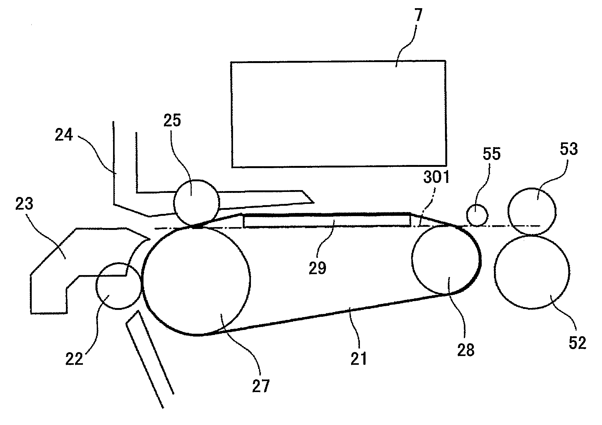
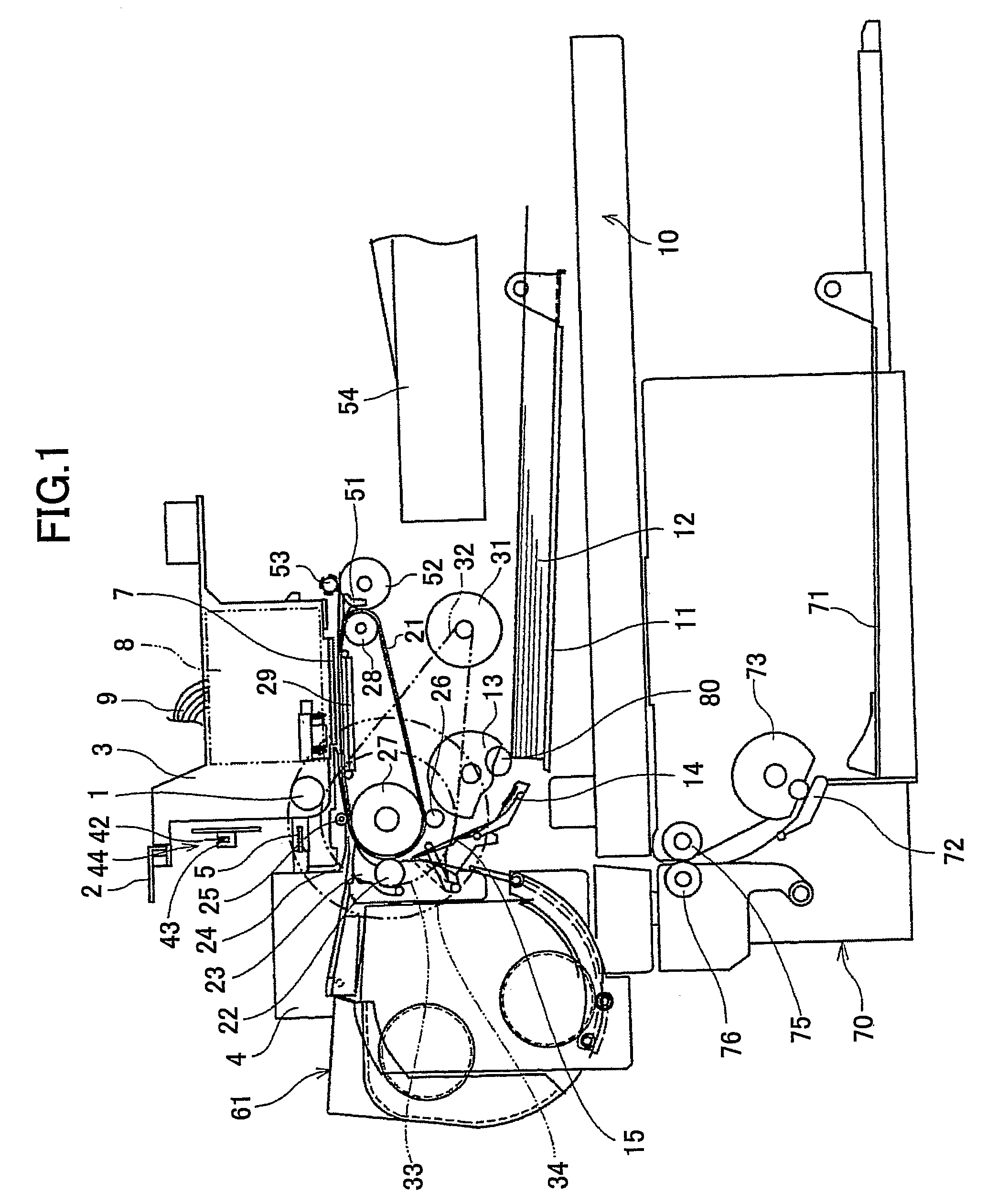
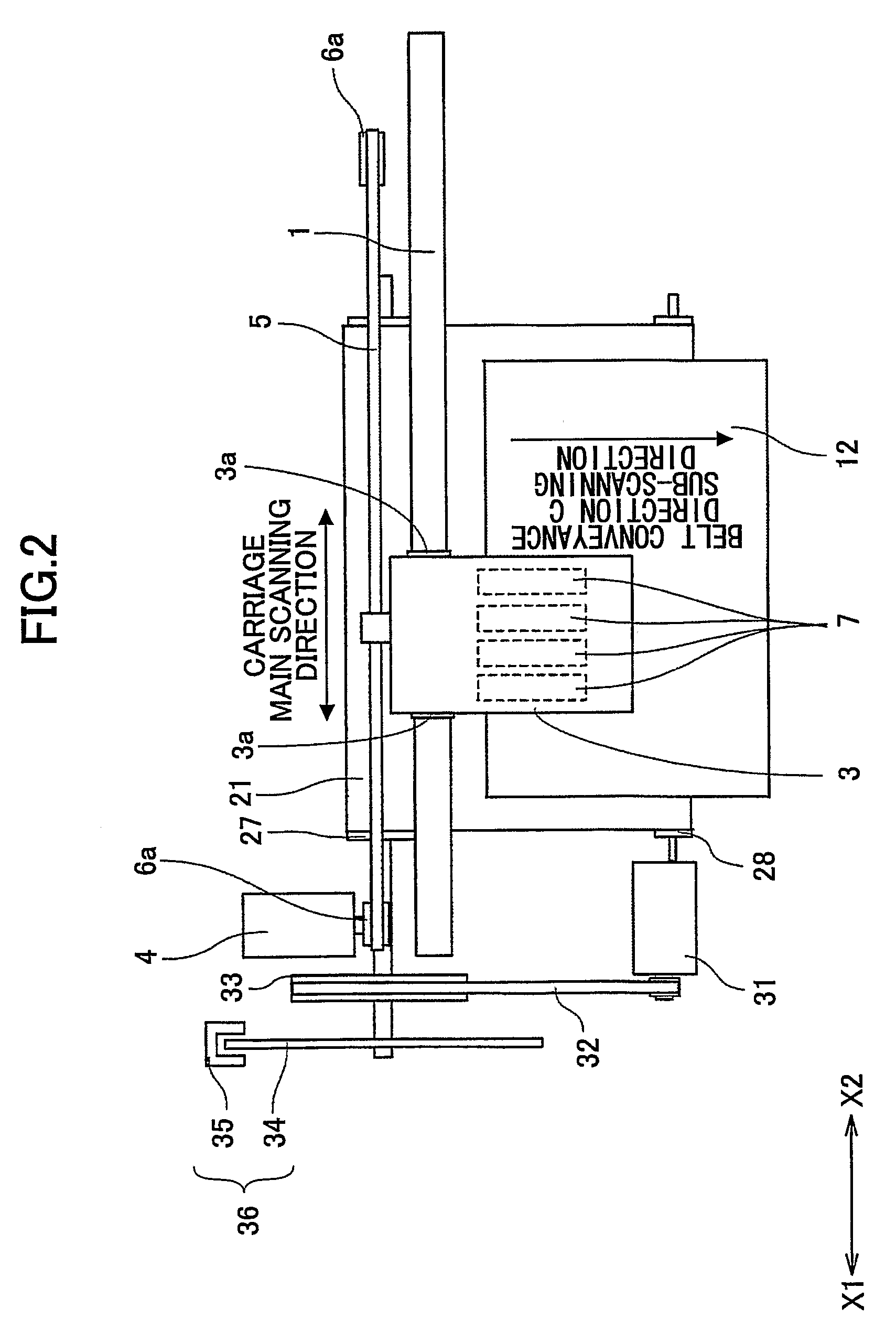
[0045]Here, FIG. 1 is a side cut-away view of a mechanism part of an image forming device of an embodiment of the present invention. FIG. 2 is a plan view of a main part of the image forming device shown in FIG. 1. FIG. 3 is an expanded side view of the main part of the image forming device shown in FIG. 1.

[0046]Referring to FIG. 1 and FIG. 2, the image forming device includes a guide rod 1 and a stay 2 provided as guide members extending between side plates (not shown in the FIG. 1 and FIG. 2) on the X1 and X2 sides. The image forming device holds a carriage 3 by the guide rod 1 and the stay 2 so that the carriage 3 can slide in a main scanning direction or the X1 and X2 directions.

[0047]A main scanning mot...


PUM


Abstract

An image forming device, includes a recording head configured to jet a liquid drop of recording liquid to a recording medium so that an image is formed; and a conveyance belt adhering the recording medium by an electrostatic force. The recording medium adhered to the conveyance belt by the electrostatic force is not separated from the conveyance belt at an angle formed by a flat surface of the conveyance belt facing the recording head and a tilt surface of the conveyance belt tilting downward at a downstream side of the recording head.

Description

TECHNICAL FIELD[0001]The present invention generally relates to image forming devices, and more specifically, to an image forming device having a conveyance belt configured to convey a recording medium.BACKGROUND ART[0002]An inkjet recording device, for example, is known as an image forming device such as a printer, facsimile, copier or a multiple function processing machine of the printer, facsimile, and copier. In the above-mentioned inkjet recording device, while a recording medium is conveyed, a liquid drop of recording liquid (hereinafter “ink drop”) is adhered to the recording medium by using a recording head (image forming part) having a liquid jet head configured to jet the liquid drop of the recording liquid, so that image forming such as recording or printing is performed. Hereinafter, the recording medium is called a paper or transferred material. However, there is no limitation of material for the paper or the transferred material.[0003]In the meantime, in a case where a...

Claims


Application Information

Patent Timeline
Patent Type & Authority Patents(United States)
IPC IPC(8): B41J2/01
CPCB41J11/007B41J11/02B41J2/01
Inventor IMOTO, SHINJIKOGURE, SEIICHI
Owner RICOH KK
Why Eureka
Try Eureka