Check patentability & draft patents in minutes with Patsnap Eureka AI!

Obstacle detection apparatus

a detection apparatus and obstacle technology, applied in underwater vessels, special data processing applications, non-deflectable wheel steering, etc., can solve the problems of high precision of detection made by this technique, and achieve the effects of high precision, reliable parking space map, and reduced tim

Inactive Publication Date: 2011-02-22
AISIN SEIKI KK
View PDF18 Cites 20 Cited by
  • Summary
  • Abstract
  • Description
  • Claims
  • Application Information

AI Technical Summary

Benefits of technology

The present invention provides an improved obstacle detection apparatus for vehicles that can detect obstacles with higher precision and reliability, while reducing the amount of calculation required. The apparatus uses a combination of distance determination and image processing to create a map of parking spaces in real-time. It uses a three-dimensional shape recognition system to detect the shape characteristics of obstacles and the edge of the obstacle with high precision. This allows for accurate parking space mapping and driving assistance. The apparatus is also designed to detect the shape of the obstacle based on the vehicle's position and the distance to the obstacle, which reduces the amount of calculation required. Overall, the invention provides an improved obstacle detection apparatus with reduced calculation load and high precision.

Problems solved by technology

However, as the parking space is displayed as a rectangular space, it cannot be said that the detection made by this technique is of high precision taking the shape characteristics of the obstacle into consideration also.

Method used


Image

  • Obstacle detection apparatus
  • Obstacle detection apparatus
  • Obstacle detection apparatus

Examples


embodiment

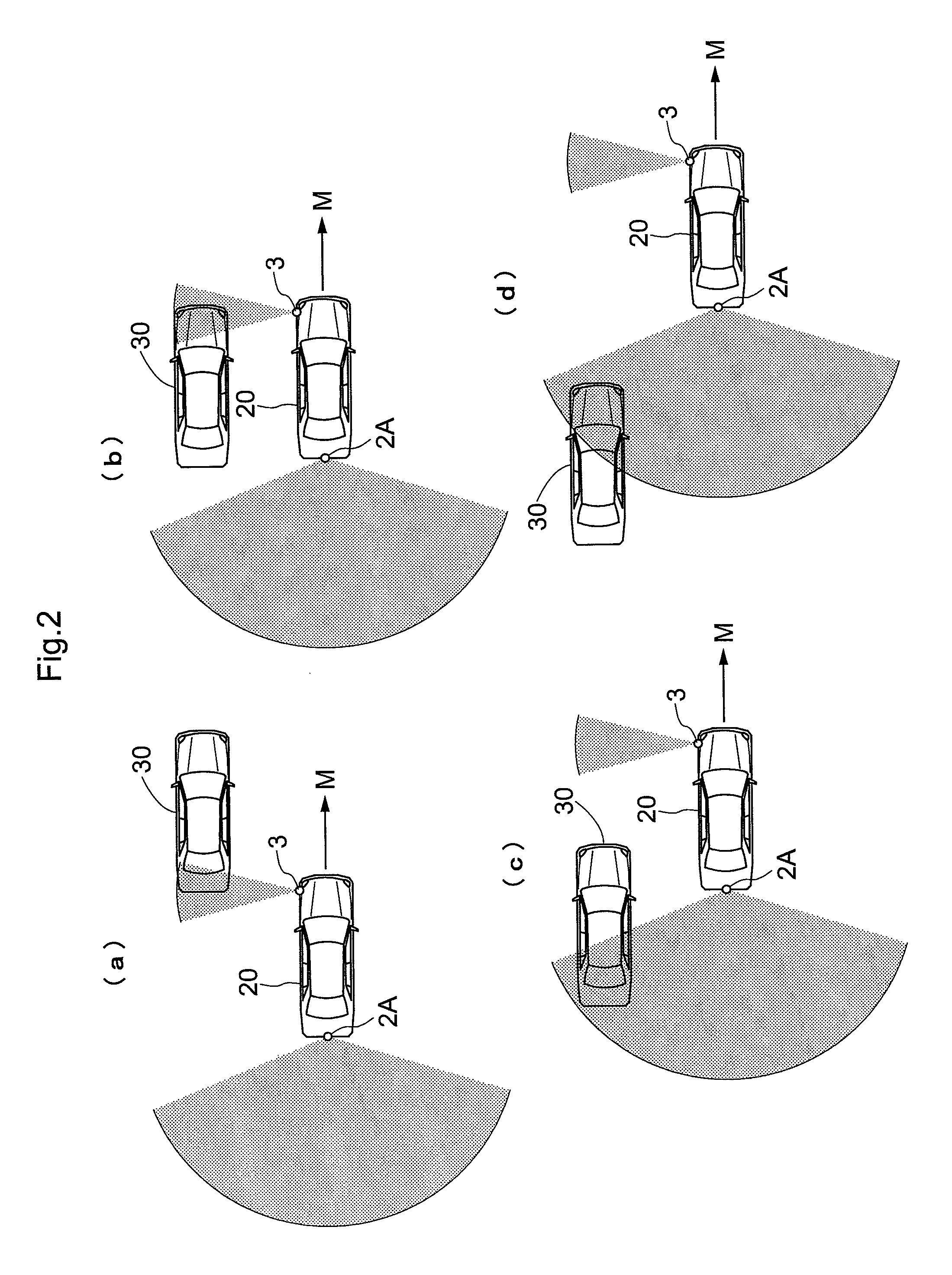
[0060]Next, as shown in FIG. 10, the present invention will be described in details with taking an example of a construction in which the vehicle 20 travels past by two parked vehicles 30 (30A, 30B) as “obstacles”, and detection is made for the two parked vehicles 30 and a space therebetween. Incidentally, the result of the detection of this construction can be utilized for assisting when the vehicle 20 makes parallel parking.

[0061]Information useful in assisting such parallel parking, as shown in FIG. 11, includes a first plane LN (longitudinal plane) indicative of the lateral faces of the parked vehicles 30A and 30B, a curve shape (surface shape) SS of a corner portion CB of the parked vehicle 30B close to the vehicle 20, a second plane LT (lateral plane) indicative of the position of the front edge of the other parked vehicle 30A far from the vehicle 20, a size of parking space PS, a longitudinal distance (overtaking distance) OD from the vehicle 20 to the parking space PS and a ...


PUM


Abstract

There is provided an obstacle detection apparatus for detecting an obstacle based on an image of periphery of a vehicle and a distance to an obstacle present in the vehicle's periphery.The apparatus includes distance determining means 3 for determining, in association with traveling of the vehicle along a direction, a distance to the obstacle present in a direction perpendicular to the vehicle traveling direction, image inputting means 2 for obtaining a peripheral image having a view angle including the obstacle, subject-vehicle position specifying means 4 for sequentially specifying a present position of the vehicle which changes in association the traveling of the vehicle, first-plane setting means 5 for setting, as a first plane, a face of the obstacle which extends perpendicular to the horizontal plane and extends, at the same time, along the traveling direction of the vehicle, plane-edge estimating means 6 for estimating an edge of the first plane relative to the vehicle moving direction, based on the distance and the position of the vehicle, image recognition area setting means 7 for setting, as an image recognition area, an area included in the peripheral image and including the plane edge, image recognizing means 8 for image-recognizing a shape characteristics of the obstacle in the image recognition area from the peripheral image, and three-dimensional shape recognizing means 9 for recognizing the obstacle three-dimensionally, based on the first plane and result of the image recognition made by the image recognizing means 8.

Description

TECHNICAL FIELD[0001]The present invention relates to an obstacle detection apparatus for detecting an obstacle, based on an image of periphery of a vehicle and a distance to an obstacle present in the vehicle's periphery.BACKGROUND ART[0002]For the purpose of detection of an obstacle present in periphery of a vehicle, both image information and distance information are important. Image information can provide distinct information for obstacle detection through driver's visual perception. Distance information is useful in determination of whether an object is located at a position where it can be potentially be an obstacle for the vehicle. The image of the vehicle's periphery is obtained by a camera mounted on the vehicle. The peripheral image thus obtained will be displayed, as it substantially is, on a display unit mounted inside the vehicle or put for use in various image recognition schemes. The distance to the obstacle present in the vehicle's periphery can be alternatively obt...

Claims


Application Information

Patent Timeline
Patent Type & Authority Patents(United States)
IPC IPC(8): G06K9/00
CPCB60R1/00G06T7/579G06K9/00201G06K9/00812G06K9/3241B62D15/029G06K9/00805G08G1/165G08G1/168B60R2300/301B60R2300/302B60R2300/305B60R2300/806B60W30/06G06K2209/23G06T2207/30264G08G1/143B60R2300/30G06V20/64G06V20/586G06V20/58G06V10/255G06V2201/08B60R1/26
Inventor KAKINAMI, TOSHIAKI
Owner AISIN SEIKI KK
Features
  • R&D
  • Intellectual Property
  • Life Sciences
  • Materials
  • Tech Scout
  • Unparalleled Data Quality
  • Higher Quality Content
  • 60% Fewer Hallucinations
Learn More