Fluid injector

a technology of injectors and fluids, which is applied in the direction of fuel injectors, liquid fuel feeders, catheters, etc., can solve the problems of high fuel resistance of the pump, and the material of the needle that is well-suited for welding is often not well-suited for reliable long-lasting operation, so as to ensure reliable operation, reduce manufacturing costs, and ensure the effect of reliable operation

Inactive Publication Date: 2011-03-01
CONTINENTAL AUTOMOTIVE ITAL
View PDF20 Cites 0 Cited by
  • Summary
  • Abstract
  • Description
  • Claims
  • Application Information

AI Technical Summary

Benefits of technology

The object of the invention is to create a fluid injector, which is simple and ensures a reliable operation for a long operating time.
The invention is distinguished by a fluid injector with an actuator unit and a cartridge which comprises a recess which forms an injection nozzle on one of its open ends and takes in a needle. The needle comprises a first and a second part, with the first part being inserted into the recess and closing or opening the injection nozzle depending on the position of the first part. The second part is coupled to the actuator unit on one of its free ends and is coupled to the first part by a coupling unit. The coupling unit is arranged in a positive connection to the first part and is joined to the second part. In that way the material of the first part may be chosen to be best suited for ensuring a reliable and wear-resistant operation of the opening and closing of the injection nozzle. On the other hand the material of the second part of the needle may be chosen to be well-suited for a joining process, in particular for a welding process. In this way, for example, a metal bellow may be joined to a second part of the needle in a reliable way.
In an advantageous embodiment of the invention the coupling unit forms a spring rest, in which a return spring rests, that urges the needle in a position where the injection nozzle is closed. In that way the coupling unit serves the double purpose of on the one hand coupling the first and second part of the needle reliably and on the other hand forming the spring rest. This has the advantage that less parts are needed for the fluid injector which results in lower manufacturing costs.
In a further advantageous embodiment of the invention a receptance is formed in the first part and fixes a keeper in axial direction relative to the needle. A coupling body, which has a recess through which the first part protrudes and which takes in the keeper and fixes it in the radial direction relative to the needle. The coupling body is joined to the second part. This has the advantage, that the coupling unit is simple to manufacture and to assemble and with a properly formed receptance tolerances in the length of the needle may be compensated for.
In a further advantageous embodiment of the invention the coupling unit is joined to the second part by welding. This has the advantage that a highly loadable connection between the second part and the coupling unit is established, which is wear-resistant even under frequent operation and under severe operating conditions.

Problems solved by technology

Piezoelectric actuators are very sensitive to fuel.
However materials for the needle that are well-suited for welding are often not well-suited for a reliable long-lasting operation of the needle in view of frequent opening and closing of the nozzle.

Method used


Image

  • Fluid injector
  • Fluid injector

Examples


Embodiment Construction

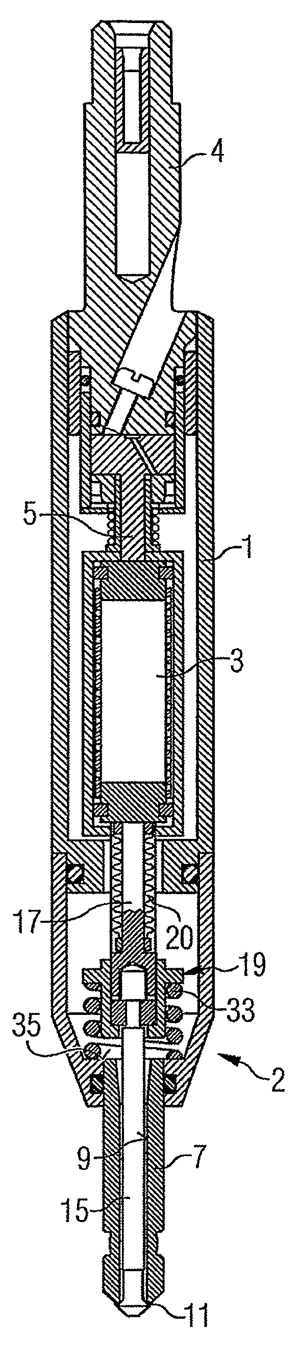
A fluid injector (FIG. 1) that is used as a fuel injector for an internal combustion engine, comprises a housing 1, a valve body 2, an actuator unit 3, a fuel connector 4 and a thermal compensator 5. The fuel connector 4 is designed to be connected to a high-pressure fuel chamber of an internal combustion engine, where fuel is stored under high pressure, for example under the pressure of about 200 Bar.

The housing 1 has a tubular shape. The fuel connector 4 is fixed to the housing 1 on one of its free ends. The thermal compensator 5 is inserted into the housing 1 and contacts the actuator unit 3. The actuator unit 3 comprises in a preferred embodiment a piezo actuator, which changes its axial length depending on a control signal applied to it. The actuator unit 3 may however also comprise another type of actuator unit, which is known to a person skilled in the art for that purpose. Such an actuator unit may be, for example, a solenoid.

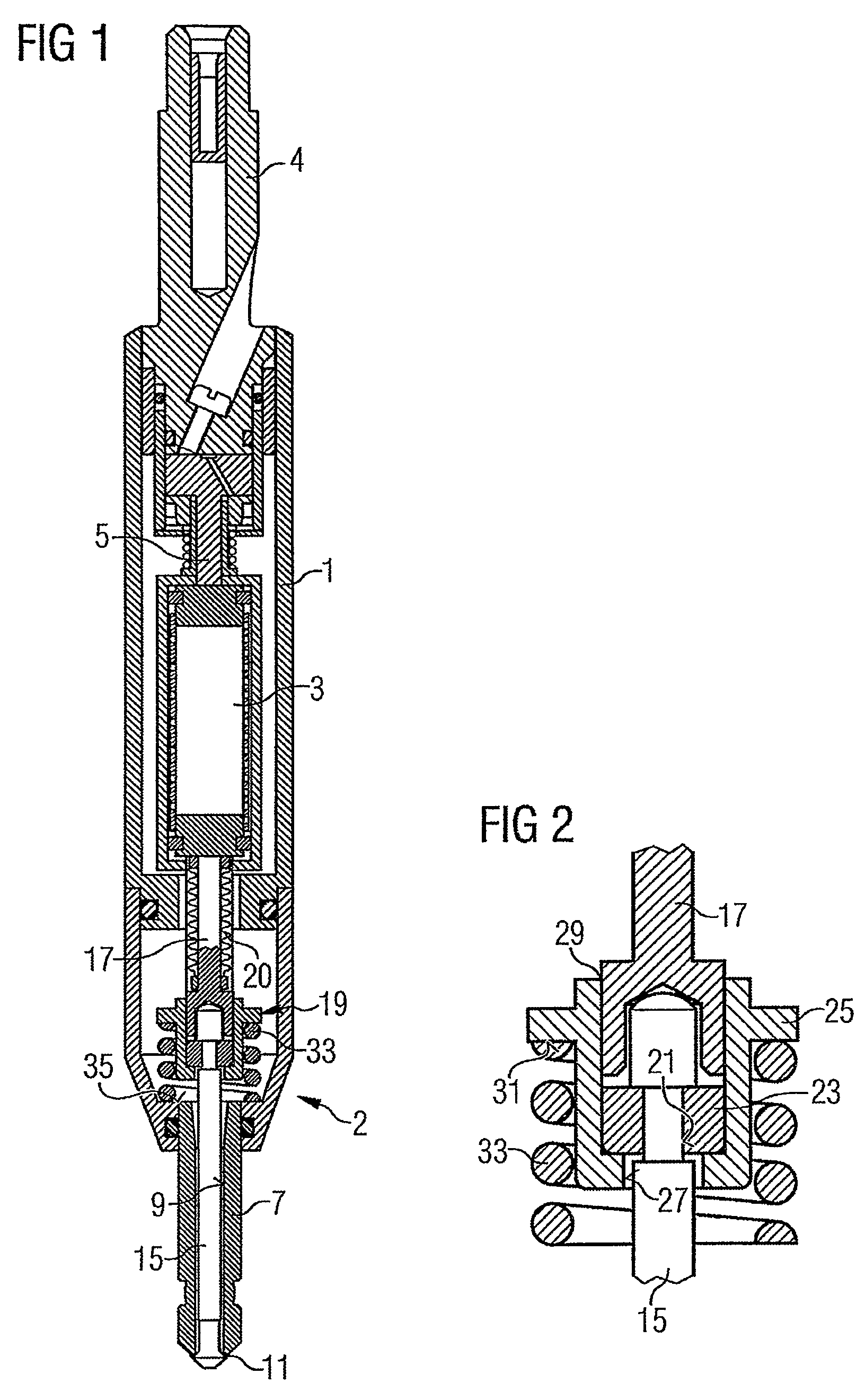
The fluid injector further comprises the valve bo...


PUM


Abstract

A fluid injector has an actuator unit, a cartridge, which has a recess, which on one of its open ends forms an injection nozzle and takes in a needle. The needle has a first and a second part (15, 17). The first part (15) is inserted into the recess and closes or opens the injection nozzle depending on the position of the first part (15). The second part (17) is coupled to the actuator unit on one of its free ends and is coupled to the first part (15) via a coupling unit. The coupling unit is arranged in positive connection to the first part (15) and is joined to the second part. In that way the material for the first part may be chosen for being highly wear resistant. On the other hand the material of the second part (17) may be chosen for being well-suited for a joining process.

Description

CROSS-REFERENCE TO RELATED APPLICATIONSThis application is a U.S. national stage application of International Application No. PCT / EP2005 / 050192 filed Jan. 18, 2005, which designates the United States of America, and claims priority to European application number EP04004592.4 filed Feb. 27, 2004 the contents of which are hereby incorporated by reference in their entirety.TECHNICAL FIELDThe invention relates to a fluid injector. Known fluid injectors comprise a housing, a valve body and an actuator unit, which is inserted into the housing. The valve body comprises a cartridge with a recess, that takes in a needle. A pretensioned spring rests on a body, that is fixed to the needle. The pretensioned return spring rests, on the other hand, on a spring rest which is formed in the valve body. In addition to that the actuator unit acts on the needle.BACKGROUNDDepending on the force balance of the actuator unit and the return spring the needle opens or closes a nozzle and in that way control...

Claims


Application Information

Patent Timeline
Patent Type & Authority Patents(United States)
IPC IPC(8): B05B1/30F02M59/00B05B1/00B05B1/32F02M51/06F02M61/08F02M61/16F02M63/00
CPCF02M51/0603F02M61/08F02M61/168F02M61/166F02M2200/701F02M63/0057
Inventor MATTEUCCI, LUCASQUARCINI, RAFFAELE
Owner CONTINENTAL AUTOMOTIVE ITAL
Why Eureka
Try Eureka