Impact absorbing member for vehicle

a technology for impact absorption and vehicle, which is applied in the direction of rubber dampers, roofs, bumpers, etc., can solve the problems of increased cost and weight, increased components, and reduced mounting capacity of crash box b>14/b>r on the vehicle, and achieve excellent impact absorption properties

Active Publication Date: 2011-03-01
NASA +1
View PDF6 Cites 38 Cited by
  • Summary
  • Abstract
  • Description
  • Claims
  • Application Information

AI Technical Summary

Benefits of technology

[0017]The present invention was accomplished against the background as above, and has an object to provide an impact absorbing member for vehicle, which is prevented from falling down laterally even when an impact load is applied thereto in an oblique direction with respect to the vehicle, so that excellent impact-absorbing properties are stably obtained, without requiring a dimensional increase in the width direction of the vehicle or the additional provision of an auxiliary member.
[0023]Therefore, even when the impact load is applied to the impact absorbing member for vehicle in an oblique direction with respect to the vehicle to generate a moment load, the existence i.e. provision of the projecting rib prevents the impact absorbing member for vehicle from falling down laterally. Accordingly, excellent impact-absorbing properties are stably obtained. This only requires formation of the projecting rib on the side wall of the tubular body portion. Accordingly, as compared with cases where the width directional dimension of the vehicle is increased or the auxiliary member is additionally provided, problems such as an increase in the number of components, the mountability deterioration on the vehicle, the increase in weight, the reduction of productivity and the like of the impact absorbing member for vehicle are alleviated or eliminated.
[0024]The projecting rib is formed without reaching i.e. so as not to reach the other axial end of the impact absorbing member for vehicle adjacent to the load input side, where the impact absorbing member starts collapsing, that is, the other axial end adjacent to the bumper member. Therefore, the load increase in the initial stage of crash can be avoided, so that the impact-energy absorbing properties (varying properties in the load and absorbed energy relative to the compression stroke) are well maintained.
[0025]According to the second aspect, the projecting dimension of the projecting rib in the direction perpendicular to the axis decreases continuously in the direction from the one axial end adjacent to the vehicle body side member to the other axial end adjacent to the side of the bumper member. Therefore, the compressive load upon collapse does not suddenly change, so that desired impact-energy absorbing properties are maintained even better.

Problems solved by technology

However, due to the increased dimension in the width direction of the vehicle, the mountability of the crash box 14R on a vehicle is degraded.
This causes problems such as an increase in the number of components followed by increases in cost and weight, the reduction of productivity, a mountability deterioration of the entire components on the vehicle, and the like.

Method used


Image

  • Impact absorbing member for vehicle
  • Impact absorbing member for vehicle
  • Impact absorbing member for vehicle

Examples


first embodiment

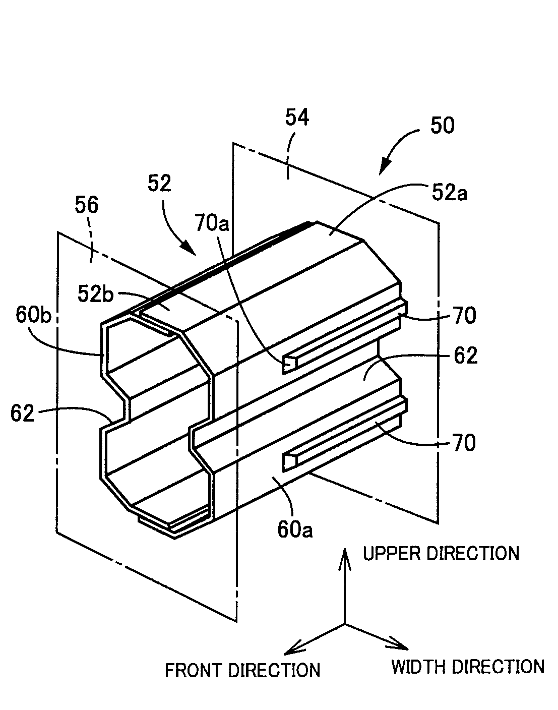
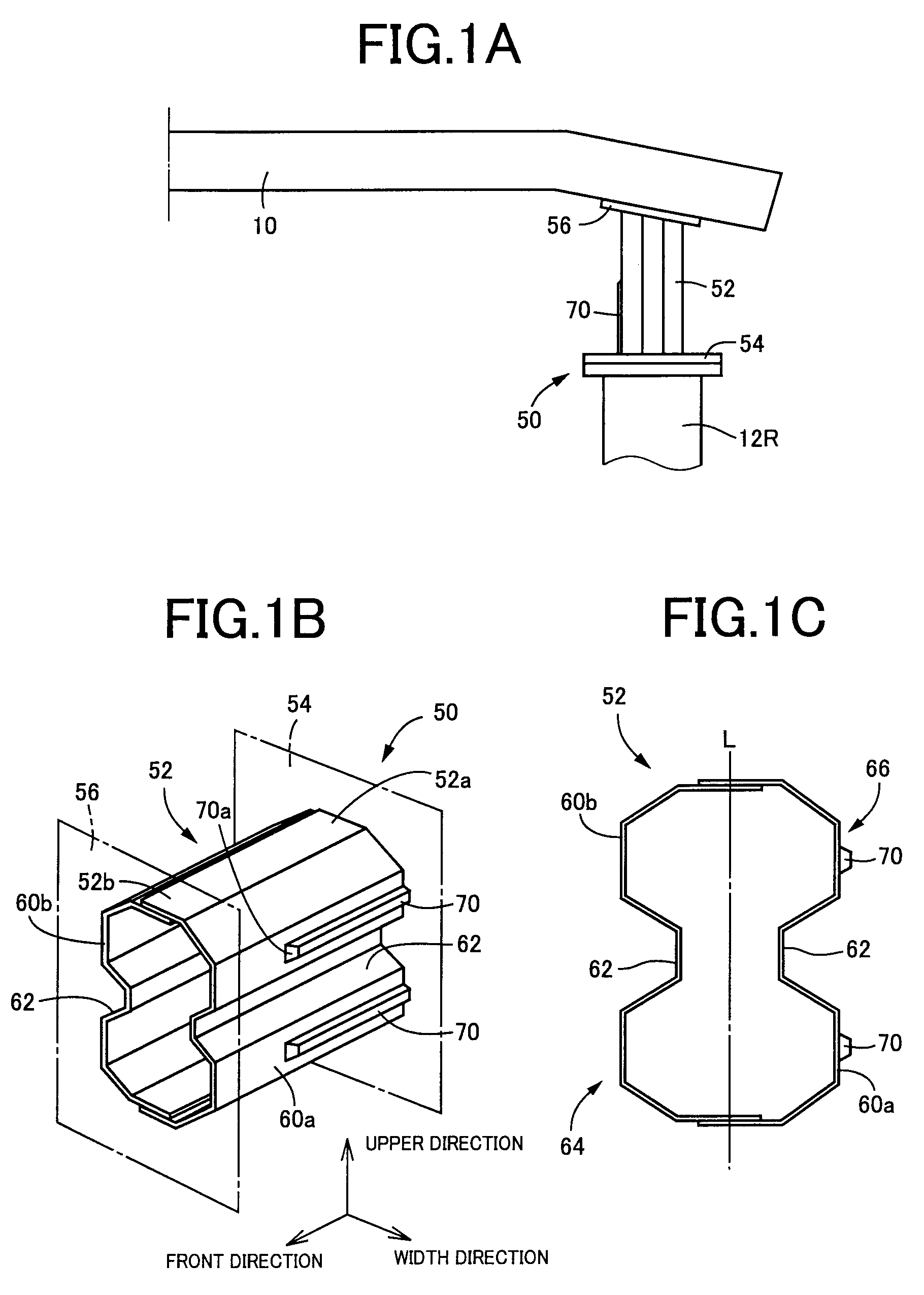
[0057]In FIGS. 1A, 1B and 1C, a crash box 50 is disposed between a side member 12R and a bumper beam 10 in place of the crash box 14R of the FIGS. 9A, 9B and 9C. The crash box 50 corresponds to an impact absorbing member for vehicle of the present invention. FIG. 1A is a plan view of the bumper beam 10 in the right half of the vehicle. The left half is constituted symmetrically about a center line. FIG. 1B is a perspective view of a body portion 52, and FIG. 1C is a front view of the same as seen from the axial direction. FIG. 1B and FIG. 1C correspond to FIG. 10A and FIG. 10B, respectively.

[0058]The crash box 50 comprises a body portion 52 having a tubular shape with a basic sectional shape of a flat octagon, and a pair of mounting plates 54 and 56 integrally weld-fixed to both axial ends (vertical ends in FIG. 1A) 52a and 52b of the tubular body portion 52, respectively. The crash box 50 is disposed between a side member 12R and a bumper beam 10, such that an axis of the body port...


PUM


Abstract

Of side wall portions (60a, 60b) of a tubular body portion (52) mainly constituting an impact absorbing member (50), a wider side wall portion (60a) on the vehicle inner side is provided with a projecting rib (70) projects outward in the direction perpendicular to the axis of the body portion. The projecting rib (70) extends from an axial end (52a) adjacent to a mounting plate (54) and parallel to the axial direction of the body portion. Therefore, even when an impact load is applied to the impact absorbing member (50) in an oblique direction with respect to the vehicle to generate a moment load, the existence of the projecting rib (70) prevents the impact absorbing member from falling down laterally. Accordingly, excellent impact-absorbing properties are stably obtained. The projecting rib (70) is formed not to reach the load input side, i.e., the axial end (52b) adjacent to a mounting plate (56), where collapse starts. Therefore, no load increase occurs in a crash initial stage to well maintain impact-energy-absorbing properties.

Description

BACKGROUND OF THE INVENTION[0001]1. Field of the Invention[0002]The present invention relates to an impact absorbing member for vehicle, for use in a vehicle for absorbing an impact applied to the vehicle. More specifically, the present invention related to a technique, applied to the case where a vehicle is subjected to an impact load obliquely from the front or back thereof, so as to prevent an impact absorbing member from falling down laterally and losing the impact-absorbing properties.[0003]2. Description of the Related Art[0004]As an impact absorbing member for vehicle, the following one is known. This impact absorbing member for vehicle has a tubular shape, and is provided with a concave groove at a portion of its side wall. The concave groove concaves inward in a direction orthogonal to an axial direction of the tubular shape (the direction perpendicular to the axis), and extends parallel to the axial direction. This impact absorbing member for vehicle is disposed between a ...

Claims


Application Information

Patent Timeline
Patent Type & Authority Patents(United States)
IPC IPC(8): B60R19/34
CPCF16F7/12
Inventor KANO, MITSUTOSHINAKANISHI, MAKOTOTAMURA, KENJI
Owner NASA
Why Eureka
Try Eureka