
Inkjet printhead board and inkjet printhead using same

a technology of inkjet printing and printhead, which is applied in the direction of printing, inking apparatus, other printing apparatus, etc., can solve the problems of affecting the size and weight reduction of the apparatus, affecting the efficiency of the printing apparatus, and affecting the cost effect, so as to achieve high reliability

Inactive Publication Date: 2011-03-01
CANON KK
View PDF18 Cites 5 Cited by
  • Summary
  • Abstract
  • Description
  • Claims
  • Application Information

AI Technical Summary

Benefits of technology

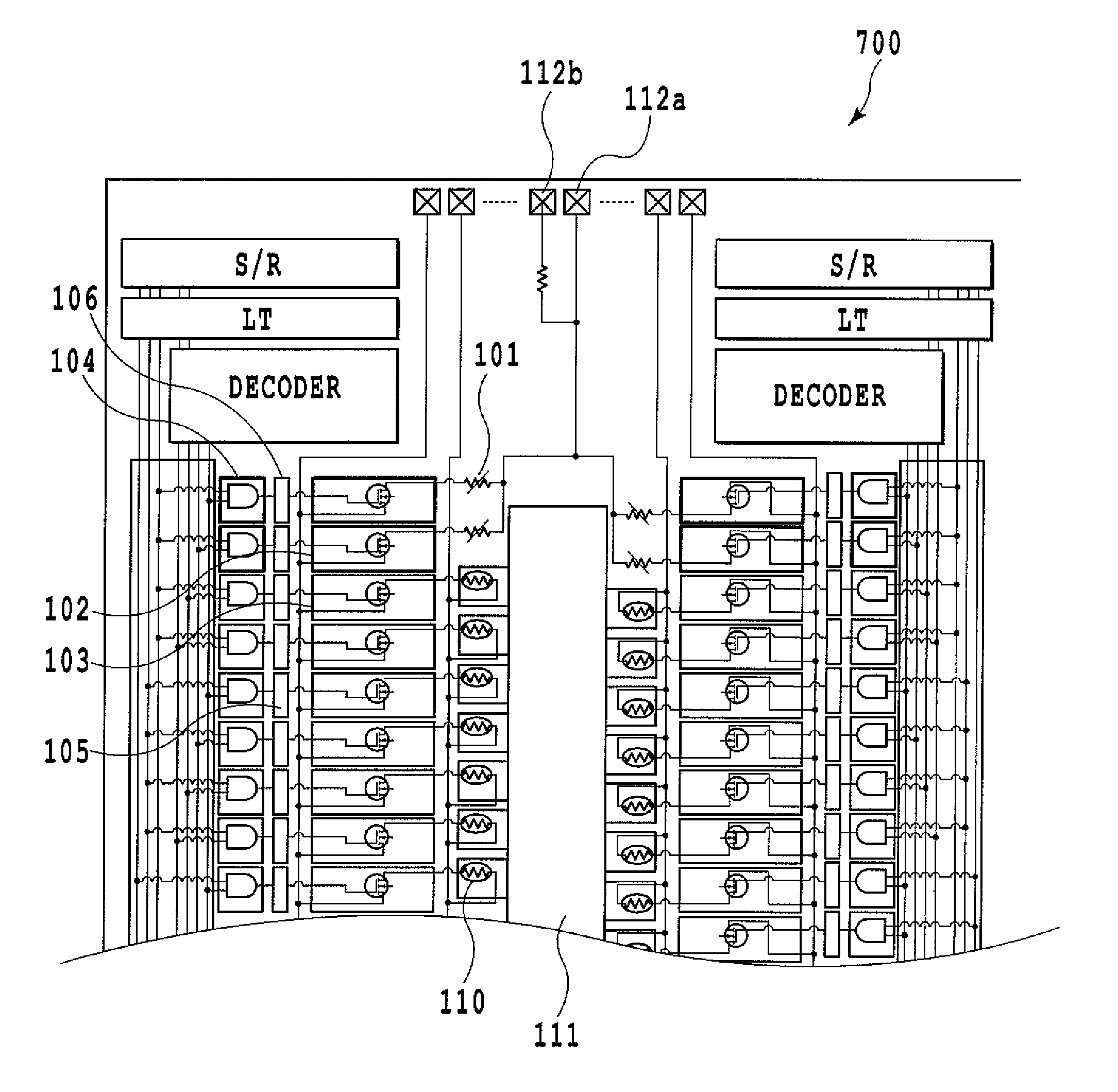
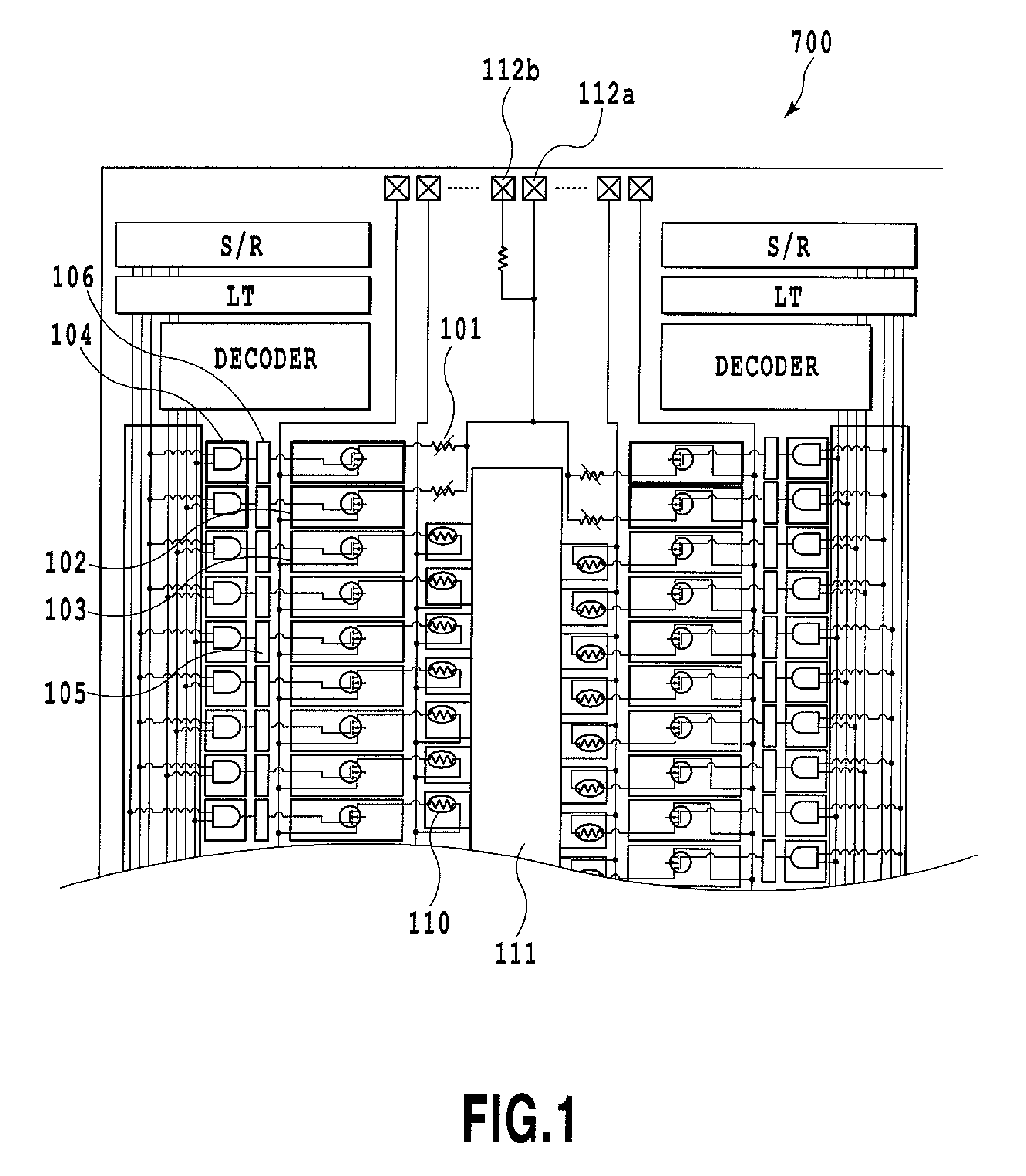
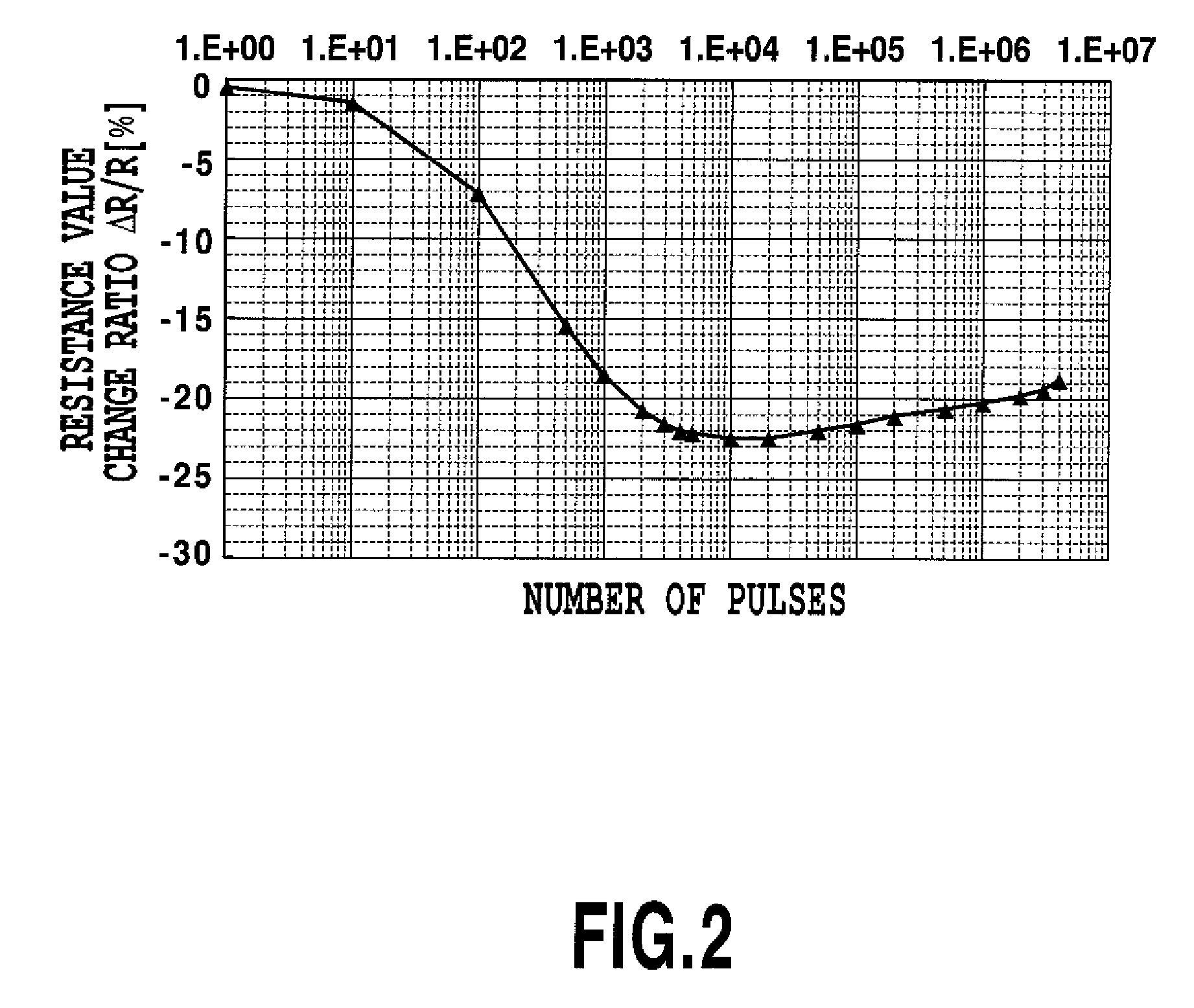
The present invention provides an inkjet printhead board with a storage element that can hold information without damaging the interlayer insulation film and protection film, and without causing significant heat generation. The invention also provides an inkjet printhead with the same printhead board. The invention uses a resistor with a resistance value that changes by conducting a thermal process as an information storage element, and the resistance value can be read out as information. This makes it possible to store information with high reliability and hold it without damaging the printhead. The invention also reduces the restriction in arranging the printhead.

Problems solved by technology

This makes structure complicate and productivity not well, thus hindering the size and weight reduction of the apparatus.
Furthermore, such a ROM is useful in storing a great capacity of information but is not favor in respect of cost where information to store is not great in capacity.
However, heat is involved in blowing the fuse elements wherein, as the fuse elements increase in the number, a greater amount of heat inevitably occurs correspondingly.
Particularly, where a logic circuit for controlling to blow the fuse elements or to read data is arranged close to the fuse element, the ink intruding through the crack reaches the logic circuit resulting in a possibility to pollute the logic circuit and raise a malfunction.
Consequently, the base plate for use in a printhead is occupied in greater part thereon by a heater power line, a logic circuit, drive elements, etc., thus making it difficult to arrange an especial fuse element in a position distant from the ink holder.

Method used


Image

  • Inkjet printhead board and inkjet printhead using same
  • Inkjet printhead board and inkjet printhead using same
  • Inkjet printhead board and inkjet printhead using same

Examples


first embodiment

[0028]With reference to the drawings, explanation will be now made in detail on a first embodiment according to the present invention.

[0029]FIG. 7 is a plan view showing an inkjet printer capable of mounting a printhead according to the present embodiment. In FIG. 7, an auto sheet feeder (ASF) 505 is stacked with printing media 508 that are to be supplied into the inkjet printer 500 by the drive of a paper feeding motor 510. Then, the printing medium 508 is conveyed to a printing site by a conveying roller 506 rotated by the drive of the conveying motor 502. The printing media 508, in the printing site, is held to form a flat printing surface by the platen, not shown.

[0030]By driving a carriage motor 504, a carriage 502 is reciprocated in a main scanning direction (in a direction of arrow α) over a guide shaft 503 through a motor pulley 507 and a timing bet 511. The carriage 502 mounts an ink cartridge 509 incorporating a printhead and an ink tank therein. Printing is to be carried ...

second embodiment

[0050]Now a second embodiment is explained.

[0051]FIG. 5 is a figure showing a printing device board 900 according to a second embodiment, which is shown to know a circuit configuration internally provided. Meanwhile, FIG. 6 is a diagram showing an equivalent circuit to the circuit that holds information with use of information storage elements 901. This embodiment is similar to the first embodiment but different in the configurational connection form of the resistors constituting the information storage element. Namely, the first embodiment juxtaposed with information storage elements 101 each configured by a single resistor, as shown in FIG. 1. On the contrary, the present embodiment has information storage element sets 901 each of which is in a form that a plurality of information storage elements are arranged in series.

[0052]In this embodiment, the information storage element set 901, provided in series on an extension of the array of electro-thermal converter elements 910, is de...


PUM


Abstract

An inkjet printhead board and inkjet printhead is provided having a reliable storage element which allows for print without causing damages to an interlayer insulation film and protection film upon printing data unique to the printhead and is free from the restriction in arrangement position. For this purpose, a printing device board uses therein an information storage element formed common in material and process to electro-thermal converter element, the resistance value of which is changed to enable information storage so that information can be read out of the information storage element.

Description

BACKGROUND OF THE INVENTION[0001]1. Field of the Invention[0002]The present invention relates to an inkjet printhead board and to an inkjet printhead using same.[0003]2. Description of the Related Art[0004]The inkjet printer is of so-called a non-impact print scheme, having features of capable of printing at high speed, capable of printing on various recording media, and less causing noise upon printing. From those, the inkjet printer is broadly employed on an apparatus acting for a print mechanism, e.g. a printer, a copier, a facsimile machine or a word processor.[0005]As for the inkjet printhead, there are known various schemes in respect of forming an ink droplet to eject. Among those, the inkjet printhead utilizing heat as ink-ejection energy realizes comparatively easily a multi-nozzle structure with high density, thus allowing for printing with high resolution and image quality at high speed.[0006]There are cases that a ROM (read only memory) is mounted on a printhead in order...

Claims


Application Information

Patent Timeline
Patent Type & Authority Patents(United States)
IPC IPC(8): B41J2/05
CPCB41J2/04541B41J2/0458B41J2/14072B41J2202/17
Inventor KUBO, KOUSUKEIMANAKA, YOSHIYUKIHATSUI, TAKUYATAKEUCHI, SOUTAYAMAGUCHI, TAKAAKIMATSUI, TAKAHIRO
Owner CANON KK
Learn More