Heat transfer device in a rotating structure

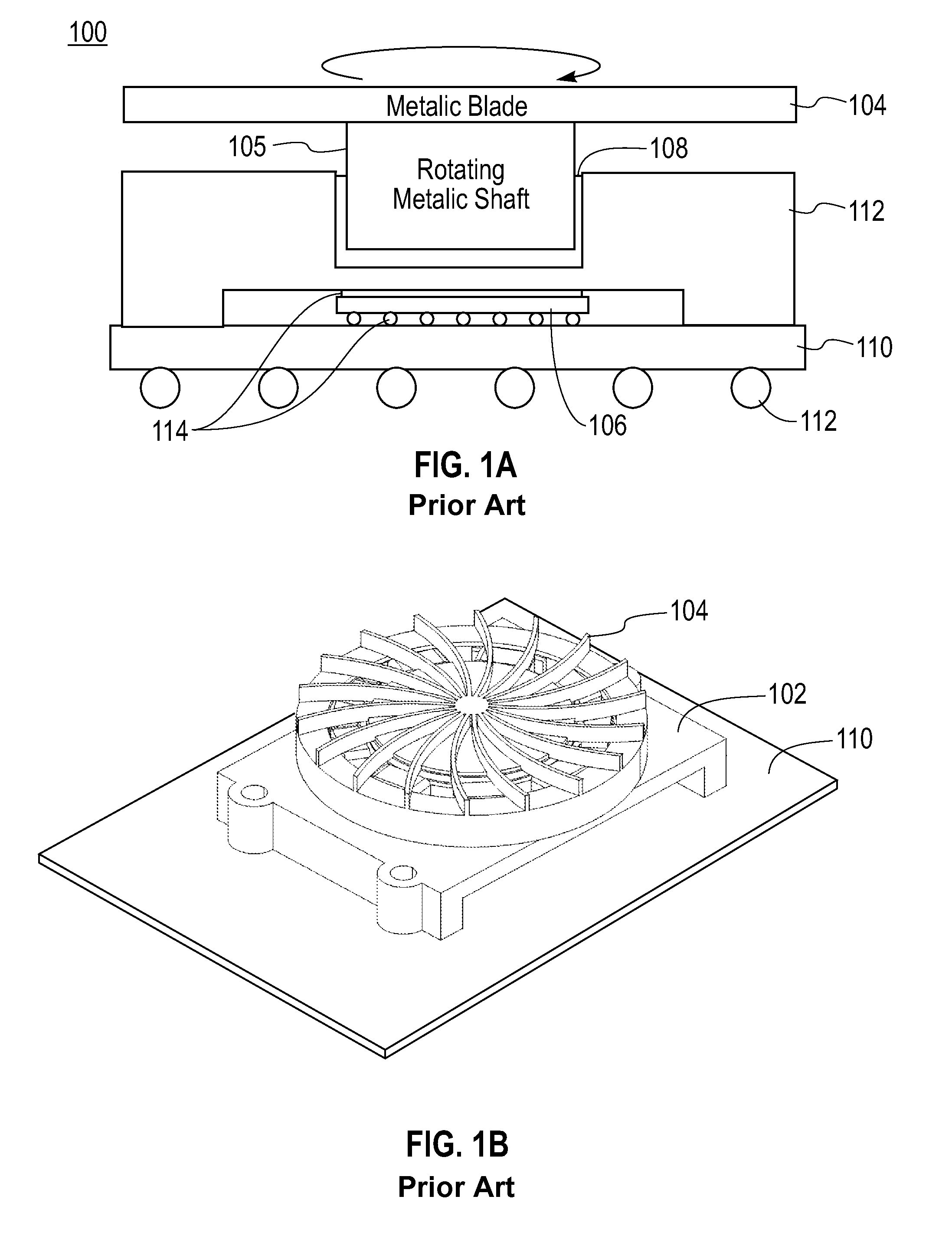
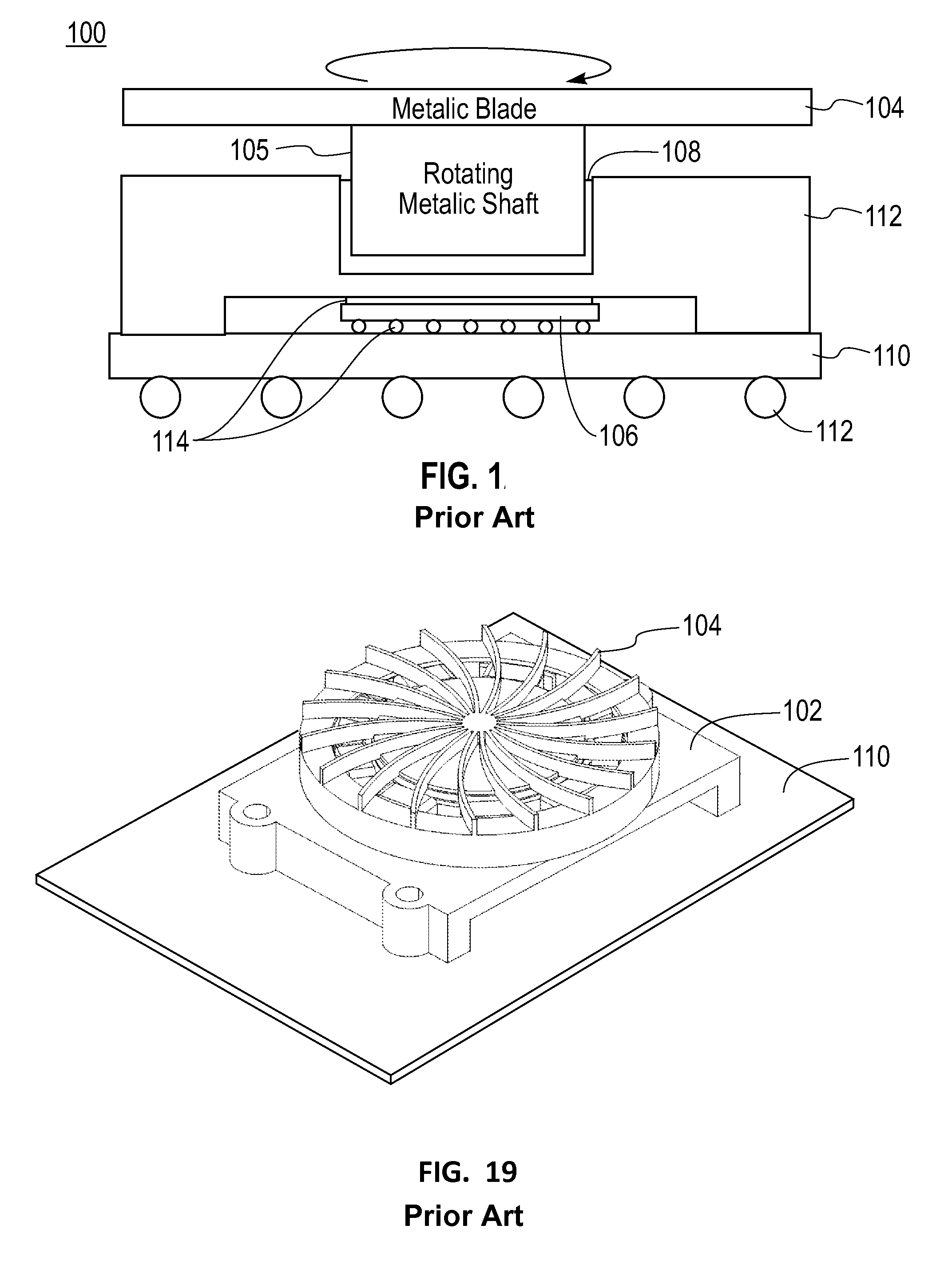
a technology of rotating structure and heat transfer device, which is applied in the direction of insulated conductors, cables, power cables, etc., can solve the problems of insufficient straight construction to ensure efficient heat transfer apparatus, limited in reducing thermal resistance, and inefficient conductivity of heat generated by chip 106/b>

Inactive Publication Date: 2011-03-01
GLOBALFOUNDRIES U S INC
View PDF17 Cites 21 Cited by
  • Summary
  • Abstract
  • Description
  • Claims
  • Application Information

AI Technical Summary

Problems solved by technology

The rotational motion of a metallic blade within a continuum of fluid (e.g., air) provides a heat transfer effect, but a straightforward construction is not sufficient to guarantee an efficient heat transfer apparatus.
A simple design where a conventional fan blade is replaced by a metallic material (with a heat conduction path) is limited in reducing the thermal resistance.
However, the heat generated by the chip 106 is not efficiently conducted away.

Method used


Image

  • Heat transfer device in a rotating structure
  • Heat transfer device in a rotating structure
  • Heat transfer device in a rotating structure

Examples


Embodiment Construction

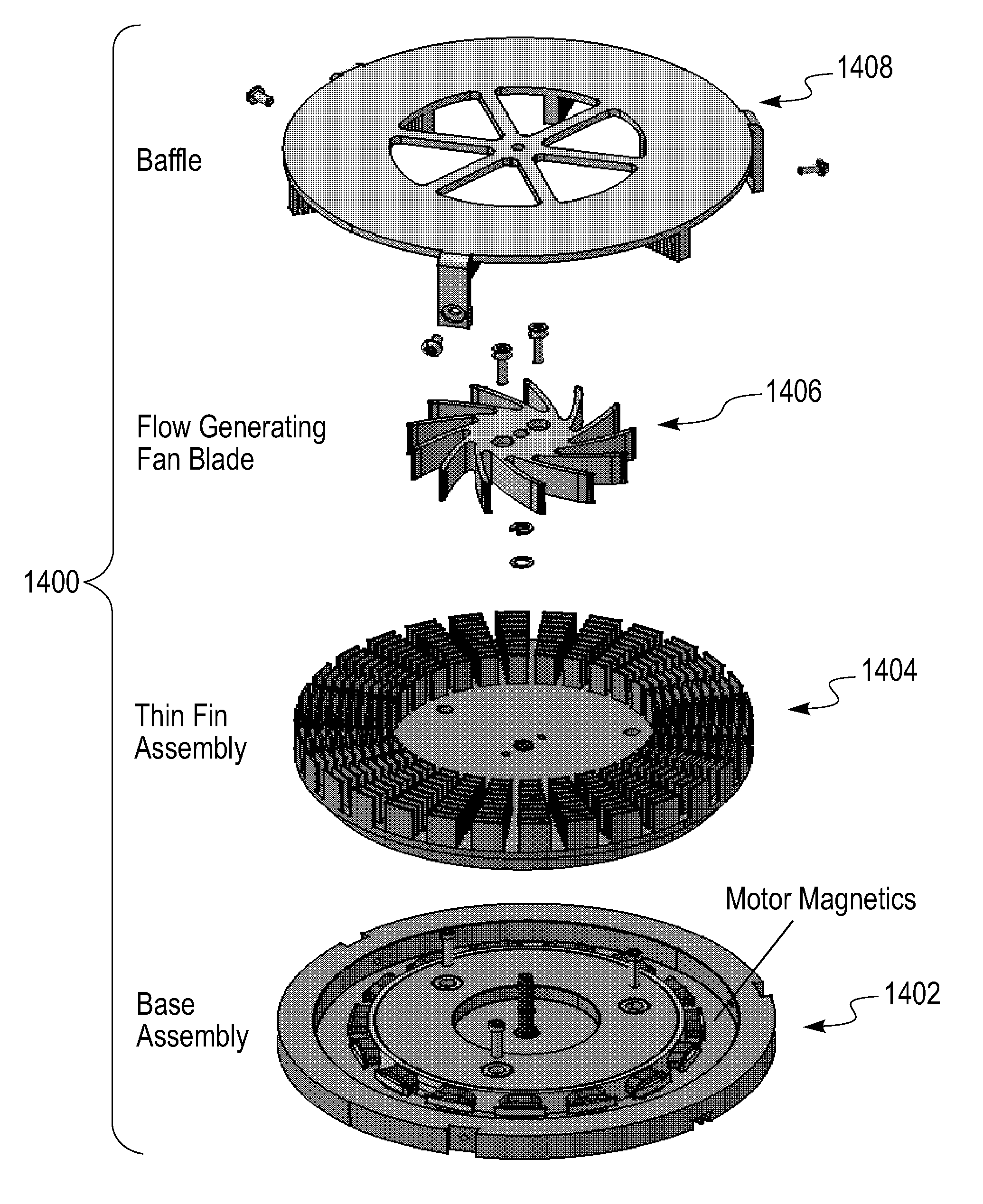
[0032]Fluid flow velocity through a rotating blade system can be decomposed into radial and tangential components. An embodiment leverages the tangential velocity component to maximize the film heat transfer coefficient. According to this embodiment, a blade structure consists of a metallic disc on which a multitude of fins or pins are distributed along concentric circles. The cross-section of the fins are optimized for maximum surface to footprint area (i.e., the area of the disk occupied by the blade). A pin with circular cross-section radius r makes the film heat transfer coefficient insensitive to airflow direction but an ultra small r could make the device mechanically weak. A thin near-rectangular (or arc-shaped) cross-sectioned fin allows large surface area for heat transfer feasible while maintaining its mechanical strength. But its geometry renders h to become sensitive to air-flow direction. The system takes advantage of the tangential velocity of a moving rotor system wit...


PUM

PropertyMeasurementUnit
heat transfer coefficientaaaaaaaaaa
temperatureaaaaaaaaaa
radiusaaaaaaaaaa

Abstract

A cooling system includes a moving rotor system which in turn includes: a disk on which a plurality of heat conducting structures are distributed, the heat conducting structures having a cross section optimized for maximum surface area to footprint area; the heat conducting structures having a shape to optimize the heat transfer coefficient between the structures moving through the ambient fluid; and a mechanism for generating a mass fluid flow over the conducting structures so that the heat conducting structures are persistently cooled.

Description

CROSS-REFERENCE TO RELATED APPLICATIONS[0001]Not applicable.STATEMENT REGARDING FEDERALLY SPONSORED-RESEARCH OR DEVELOPMENT[0002]Not applicable.INCORPORATION BY REFERENCE OF MATERIAL SUBMITTED ON A COMPACT DISC[0003]Not Applicable.FIELD OF THE INVENTION[0004]The invention disclosed broadly relates to the field of cooling devices and more specifically, to cooling devices for use in integrated circuits.BACKGROUND OF THE INVENTION[0005]The rotational motion of a metallic blade within a continuum of fluid (e.g., air) provides a heat transfer effect, but a straightforward construction is not sufficient to guarantee an efficient heat transfer apparatus. The blade geometry of the fan requires an appropriate structure to impart maximum heat to the ambient. A simple design where a conventional fan blade is replaced by a metallic material (with a heat conduction path) is limited in reducing the thermal resistance. A film heat transfer coefficient (h) of the order of 50 Watts / m2K for a convent...

Claims


Application Information

Patent Timeline
Patent Type & Authority Patents(United States)
IPC IPC(8): F04D29/58H05K7/20
CPCF04D25/04F04D29/582H01L23/467Y10T29/49236H01L2224/73253H01L2924/15311H01L2924/16152H01L2224/16H01L2924/00014H01L2924/00011H01L2224/0401
Inventor KHANNA, VIJAYESHWAR D.MCVICKER, GERARDSRI-JAYANTHA, SRI M.
Owner GLOBALFOUNDRIES U S INC
Why Eureka
Try Eureka