Retaining member electric component and electric device

a technology of electric components and retaining members, which is applied in the direction of coupling device connections, printed circuit aspects, printed circuit manufacturing, etc., can solve the problems of low easy and easy pulling of electric components from the substrate, so as to improve the retaining strength of electric components to the substrate and reduce damage to the side wall of the opening

Inactive Publication Date: 2011-03-01
DENSO CORP
View PDF38 Cites 4 Cited by
  • Summary
  • Abstract
  • Description
  • Claims
  • Application Information

AI Technical Summary

Benefits of technology

In the above configuration, the retaining strength of the electric component to the substrate can be improved, and damage of a side wall of the opening can be decreased.

Problems solved by technology

That is, retaining strength of the electric component to the substrate is low and the electric component is pulled out from the substrate easily.
That is, the side wall of the opening is easily damaged.

Method used


Image

  • Retaining member electric component and electric device
  • Retaining member electric component and electric device
  • Retaining member electric component and electric device

Examples


first embodiment

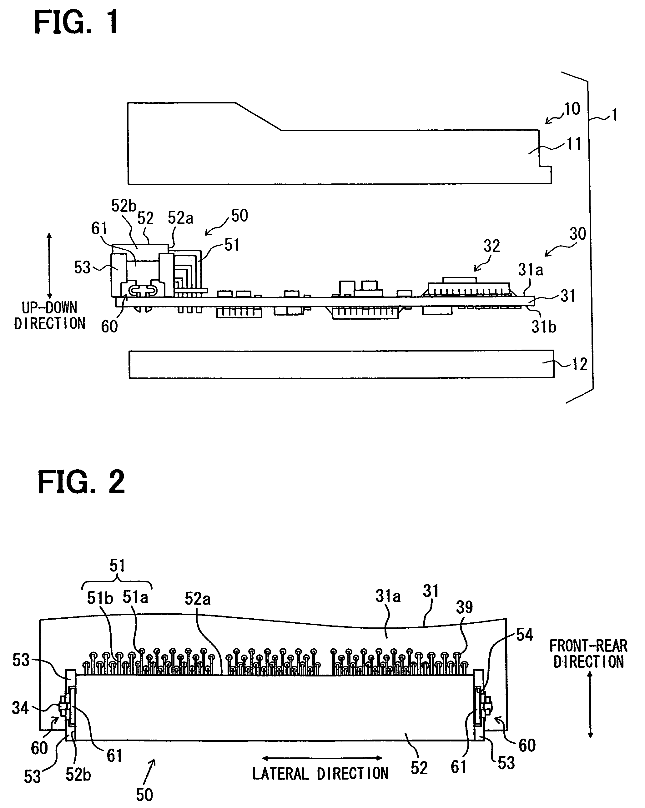
Hereinafter, a first embodiment of the present invention will be described with reference to FIG. 1 to FIG. 7. As shown in FIG. 1, a thickness direction of a substrate indicates an up-down direction. As shown in FIG. 2, a terminals arranging direction in a housing 52 or a longitudinal direction of the housing 52 indicates a lateral direction, and a direction perpendicular to the up-down direction and the lateral direction indicates a front-rear direction or a latitudinal direction of the housing.

In following embodiments, the retaining member has significant features, and a connector including the retaining member and an electric device including the retaining member will be described. The electric device is an electric control device having a non-waterproof structure, and is used as an engine ECU, i.e., Electric Control Unit, of vehicles, for example.

An electric control device 1 shown in FIG. 1 includes a circuit board 30, in which an electric component 32 is mounted on a substrate ...

second embodiment

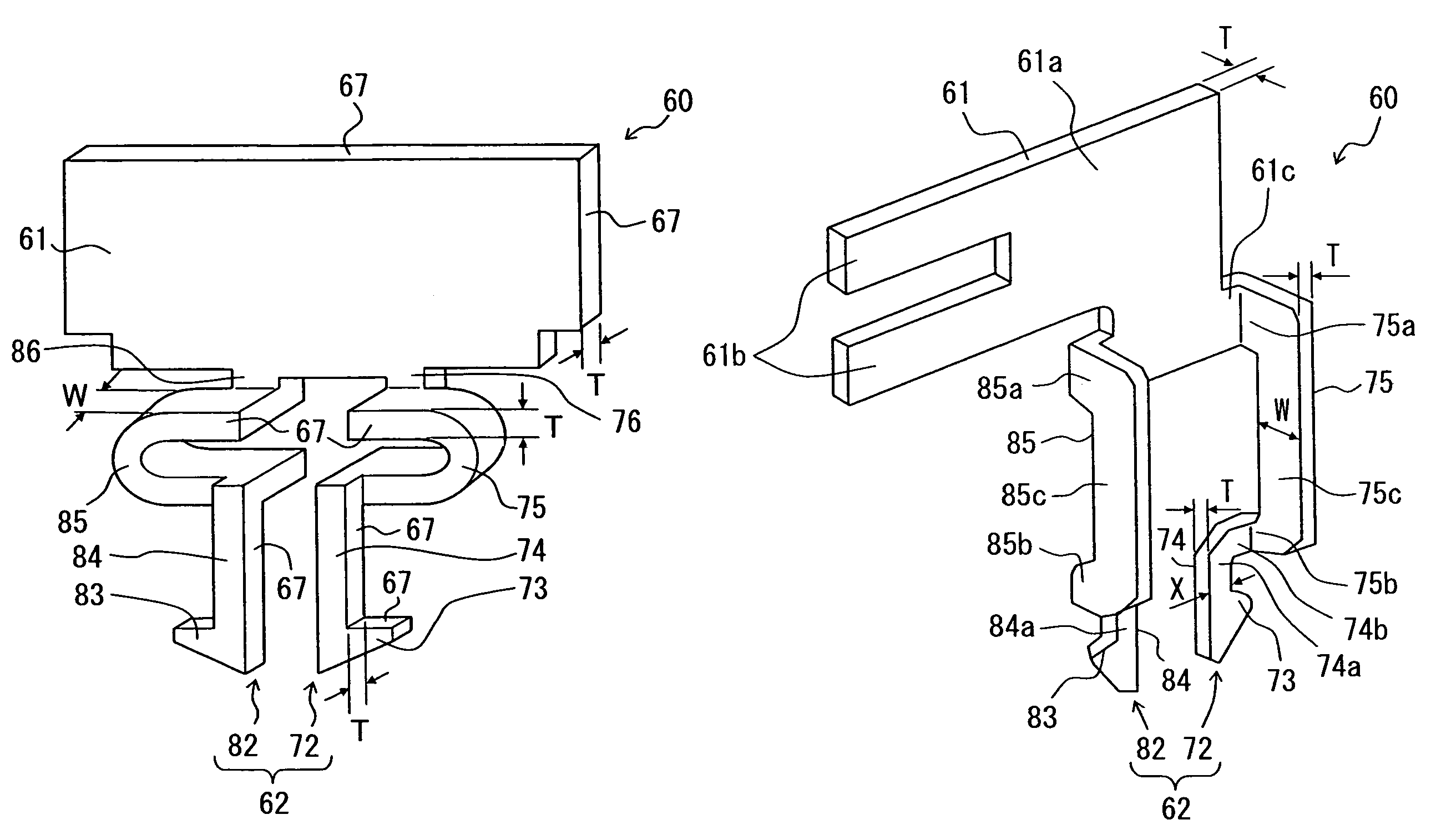
Next, a second embodiment of the present invention will be described with reference to FIG. 8 to FIG. 11.

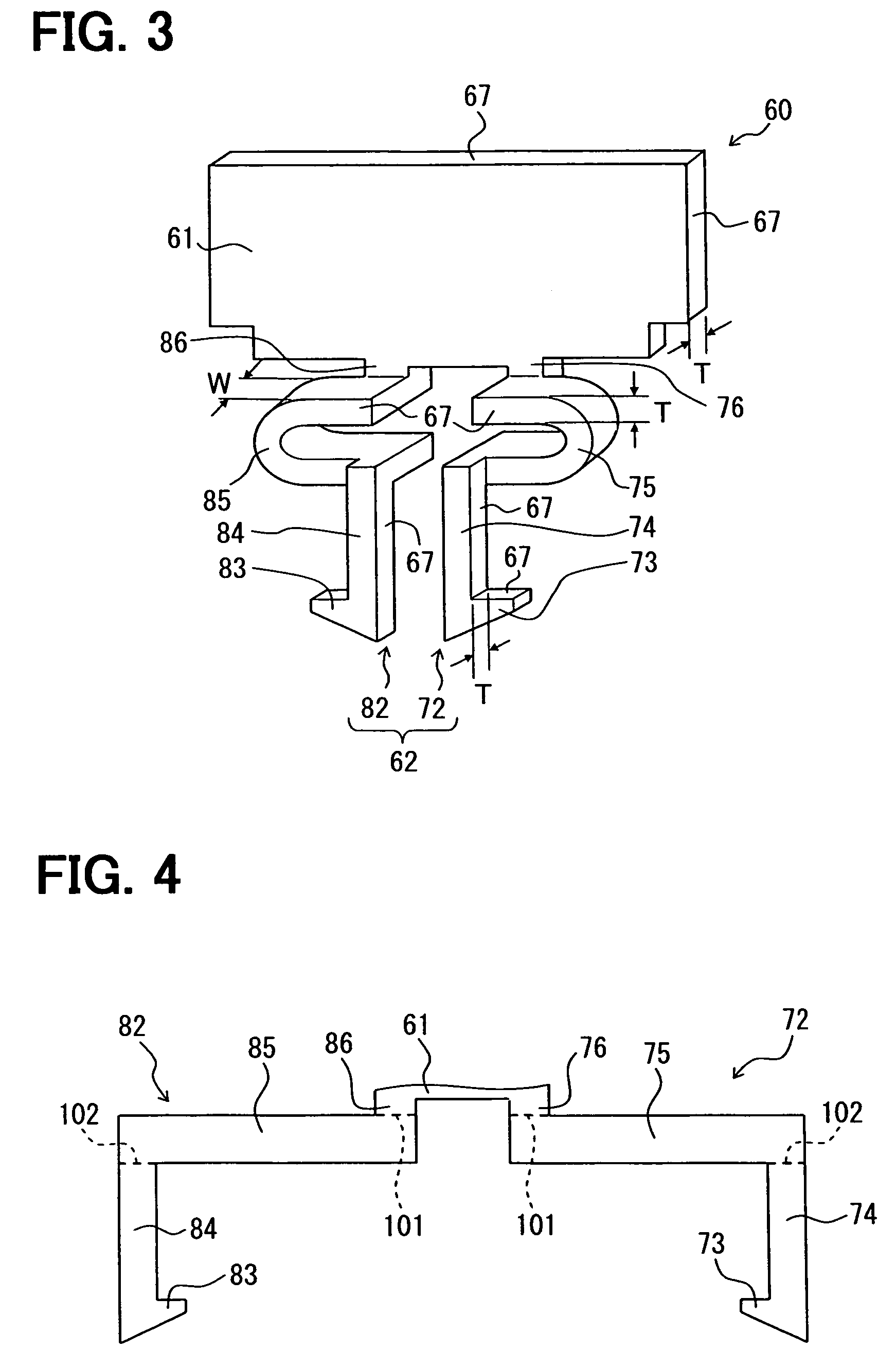
Although the spring portion 65 of the first embodiment is substantially U-shaped, the spring portion 65 may be an arbitrary form as long as the latch portion 63 and the coupling portion 64 can be inserted into the opening 34 and the latch portion 63 can be disposed on the rear face 31b of the substrate 31 by the displacement of the spring portion 65. In the present embodiment, as shown in FIG. 8, a flat plate spring is used as the spring portion 65. The pair of the first leg portions 72 and 82 is extended form the same base portion 61.

Specifically, taking one first leg portion 72 as an example, the bonding portion 76 having a crank shape is extended downwardly from the substantially rectangular flat plate-like base portion 61 in the same plane with the base portion 61. The bonding portion 76 is bent substantially 90 degrees so that the flat plate spring portion 75 is extended fro...

third embodiment

Next, a third embodiment of the present invention will be described with reference to FIG. 12 to FIG. 13B.

FIG. 12 shows that an edge portion 73b of the latch portion 63, i.e., the pair of latch portions 73 and 83, is angular-shaped, that is, an angle below 90 degrees. When the first leg portion 62, i.e., the pair of first leg portions 72 and 82, is inserted into the opening 34 and the latch portion 63 passes through the opening 34, a part of the latch portion 63 shifts to the outside from the opening 34 by reactive force or restoring force of the spring portion 65, i.e., the pair of spring portions 75 and 85. Therefore, the edge portion 73b may scratch a metal coating layer 37a formed on an end portion of the side wall of the opening 34 of a metal coating layer 37. The metal coating layer 37 is disposed on the side wall and at the periphery of the opening 34. In FIG. 12, a solid line represents the first leg portion 62 just before the latch portion 63 passes through the opening 34, ...


PUM


Abstract

A retaining member includes at least a leg portion having a latch portion, a coupling portion and a spring portion. When the spring portion is displaced, the coupling portion is twisted. Then, the latch portion and the coupling portion are inserted into the opening so that an electric component is retained on a main face of the substrate. In this state, a part of the latch portion is disposed at the periphery of the opening on a rear face of the substrate, a part of the coupling portion is disposed in the opening, and the spring portion is disposed on the main face of the substrate. Therefore, the retaining strength of the electric component to the substrate can be improved, and damage of a side wall of the opening can be decreased.

Description

CROSS REFERENCE TO RELATED APPLICATIONSThe present application is based on Japanese Patent Applications No. 2008-8360 filed on Jan. 17, 2008, and No. 2008-166454 filed on Jun. 25, 2008, the disclosures of which are incorporated herein by reference.FIELD OF THE INVENTIONThe present invention relates to a retaining member, an electric component and an electric device.BACKGROUND OF THE INVENTIONA conventional retaining member included in an electric component is partially deformed by elastic force and inserted into an opening in a substrate, and the electric component is retained on the substrate by reactive force or restoring force generated by the deformation of the retaining member. For example, JP-A-2007-128772 discloses that a metal plate is punched out in a die cutting process, and then, pressure is applied to the metal plate and the metal plate is bent so that the retaining member is formed. A pair of first leg portions extends in the same direction from a flat plate-like base p...

Claims


Application Information

Patent Timeline
Patent Type & Authority Patents(United States)
IPC IPC(8): H01R13/60H01R12/71
CPCH05K3/301H01R12/7029H05K2201/10189H05K2201/10598
Inventor KONDO, MITSUAKIHONDA, TAKAYOSHIOONISHI, KOUJI
Owner DENSO CORP
Why Eureka
Try Eureka