System, method, and apparatus for pre-tensioned pipe for load-sharing with composite cover

a technology of riser pipes and composite covers, applied in the field of reinforced pipes, can solve the problems of pipe bending moments, high axial tension and bending moments, and high internal pressure, and achieve the effect of improving load sharing and preventing material yielding

Inactive Publication Date: 2011-03-01
VETCO GRAY
View PDF3 Cites 2 Cited by
  • Summary
  • Abstract
  • Description
  • Claims
  • Application Information

AI Technical Summary

Benefits of technology

[0007]Embodiments of a system, method, and apparatus for pre-stressing the interface between a pipe and composite wrap on the pipe are disclosed. The invention improves the load sharing between the two materials and thereby prevents yielding of the materials. In one embodiment, the pipe is put in tension prior to being circumferentially wrapped with a composite material, such as a carbon fiber-based product. After the pipe is wrapped and the pre-tension is relieved, a pre-stressed interface between the pipe and composite is achieved.
[0012]In still another embodiment, the length and diameter of the pipe is reduced prior to wrapping by significantly reducing a temperature of the pipe. The cooling operation may be performed by extreme freezing in a chamber, or a continuous supply of a cold medium to the ID of the pipe (such as liquid nitrogen). The cold temperatures may reduce curability of some composite matrix materials (e.g. heat-cured epoxy). However, matrix materials other than heat-cured epoxies (e.g., UV-cured epoxies) may be used. In addition, the pipe axially expands upon re-warming, causing an axial pretension in the composite wrap.

Problems solved by technology

The composite is strictly limited to increasing the hoop stress capacity of the pipe.
During service, the pipe is subjected to high axial tension and bending moments, extremely high internal pressures, and environmental fatigue loads.

Method used


Image

  • System, method, and apparatus for pre-tensioned pipe for load-sharing with composite cover
  • System, method, and apparatus for pre-tensioned pipe for load-sharing with composite cover
  • System, method, and apparatus for pre-tensioned pipe for load-sharing with composite cover

Examples


Embodiment Construction

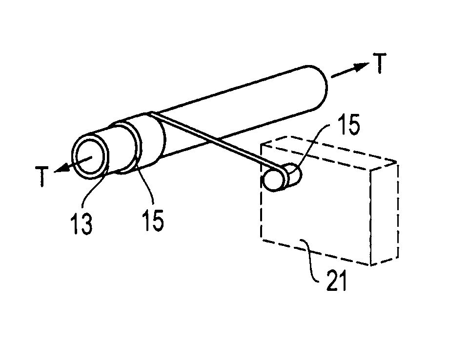
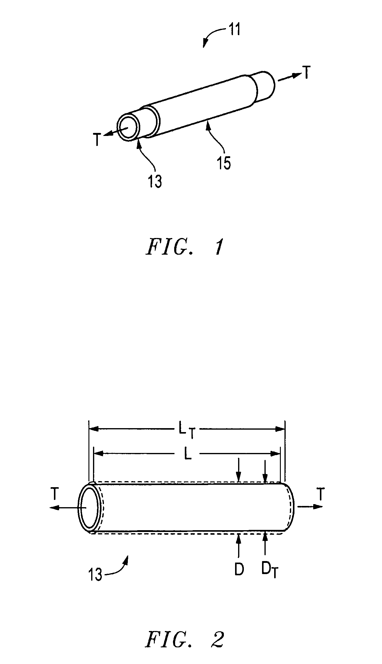
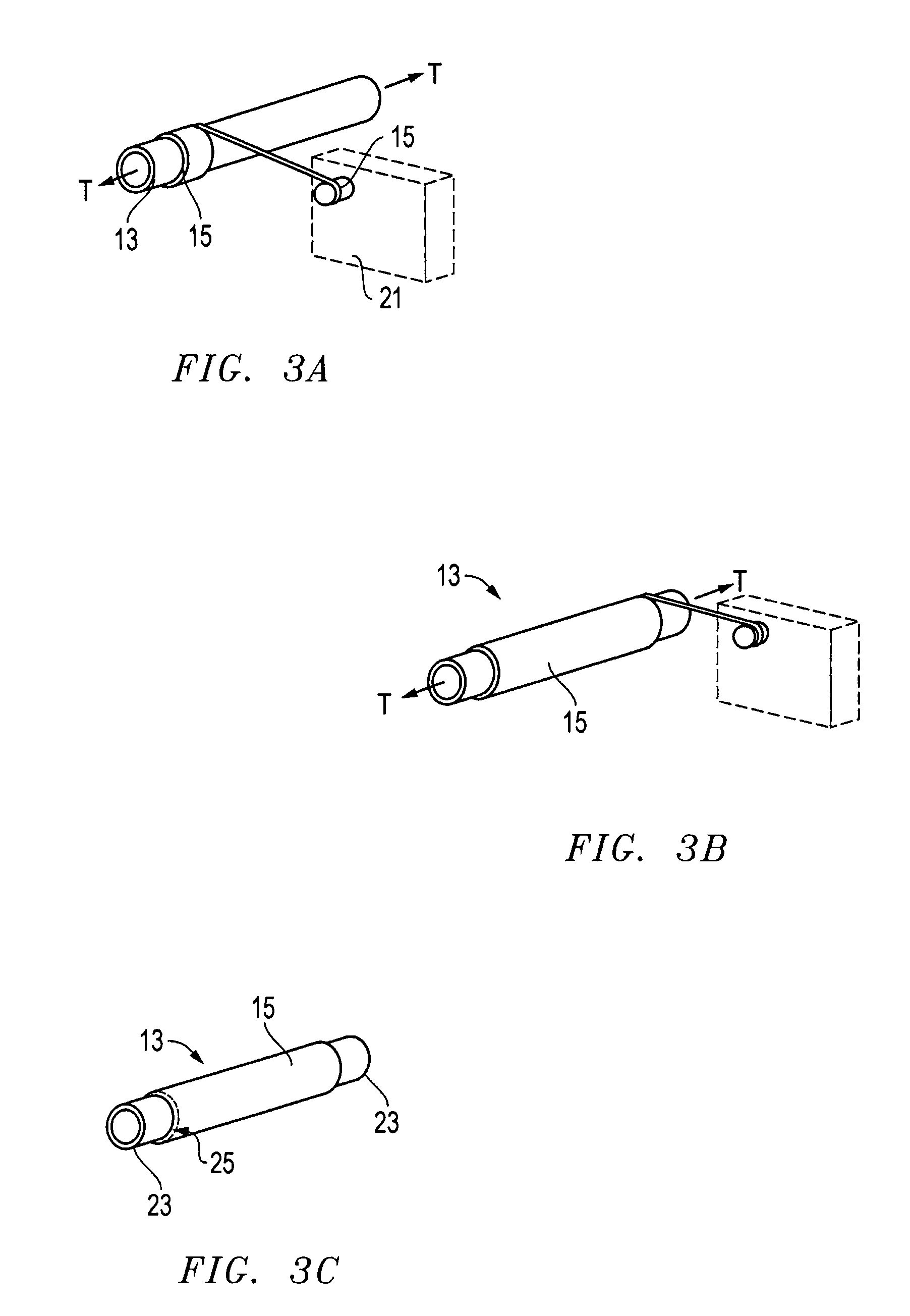
[0024]Referring to FIG. 1, one embodiment of an assembly 11 comprising a composite-wrapped pipe 13 is shown. The letter “T” represents tension being applied to the pipe section along a longitudinal axis thereof. Although the pipe is schematically illustrated without end connections, some applications of the pipe may be fitted with connectors or other means of joining pipe sections together along their axes. The pipe also includes a composite fiber-matrix material 15 that is overlaid on top of the pipe's outer diameter (OD).

[0025]FIG. 2 illustrates the effects of applying axial tension T to pipe 13. As the pipe is placed in tension it stretches in the direction that the load T is applied. Because the volume of material cannot change, the pipe deflects inward for a reduction in diameter. This is known as Poisson's effect. Thus, when a pipe of original length L and diameter D is placed under axial tension T, the pipe expands to length LT and reduces in diameter to DT, where LT>L and D>...


PUM

PropertyMeasurementUnit
inner diameteraaaaaaaaaa
outer diameteraaaaaaaaaa
tensionaaaaaaaaaa

Abstract

A pipe is wrapped with a composite to form a pre-stressed interface to facilitate load sharing between the materials. Prior to being wrapped, the pipe is placed in tension via hydraulic devices or the like. Alternatively, a combination of cured and uncured composite wraps is used in proximity to each other to apply compressive stress to the pipe. In addition, the pipe may be subjected to cold temperatures to change its dimensions prior to being wrapped with a composite material.

Description

BACKGROUND OF THE INVENTION[0001]1. Technical Field[0002]The present invention relates in general to reinforced pipes and, in particular, to an improved system, method, and apparatus for pre-tensioning riser pipes to share load with composite covers.[0003]2. Description of the Related Art[0004]In the prior art, the internal pressure capacity of steel alloy risers may be increased by wrapping the outer diameters (OD) of the risers with a composite material, such that the pressure capacity is shared by the steel pipe and the composite wrap. For example, in one application a pipe is wrapped with a carbon-fiber and epoxy matrix composite that is applied to the OD. The composite is strictly limited to increasing the hoop stress capacity of the pipe. In addition, a fiberglass covering can be applied over the top of both the composite and the pipe to provide damage protection.[0005]During service, the pipe is subjected to high axial tension and bending moments, extremely high internal pres...

Claims


Application Information

Patent Timeline
Patent Type & Authority Patents(United States)
IPC IPC(8): B65H81/00
CPCB29C63/10
Inventor PALLINI, JOSEPH W.ELLIS, FIFE B.HAVELKA, DANNY L.MUNK, BRIAN N.
Owner VETCO GRAY
Why Eureka
Try Eureka