Mandrel locking unit for printing roller mandrels in a rotary printing machine

Inactive Publication Date: 2011-03-08
WINDMOELLER & HOELSCHER GMBH
View PDF9 Cites 3 Cited by
  • Summary
  • Abstract
  • Description
  • Claims
  • Application Information

AI Technical Summary

Benefits of technology

[0009]Therefore, the objective of the present invention is to suggest a man

Problems solved by technology

However, the disadvantage of this design is that the mandrel-locking unit has an overall depth that results from its design and that is composed of the depth of the bearing piston and the maximum stroke of the piston cylinder unit.
This overall depth brings abou

Method used


Image

  • Mandrel locking unit for printing roller mandrels in a rotary printing machine
  • Mandrel locking unit for printing roller mandrels in a rotary printing machine

Examples


Embodiment Construction

[0025]Further scope of applicability of the present invention will become apparent from the detailed description given hereinafter. However, it should be understood that the detailed description and specific examples, while indicating preferred embodiments of the invention, are given by way of illustration only, since various changes and modifications within the spirit and scope of the invention will become apparent to those skilled in the art from this detailed description.

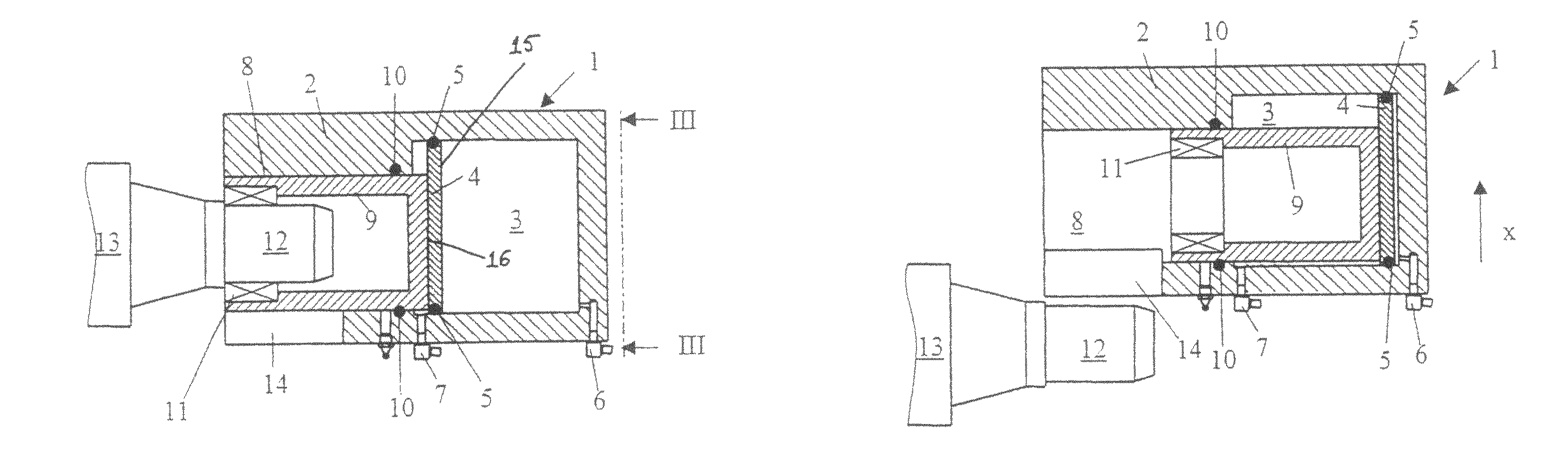
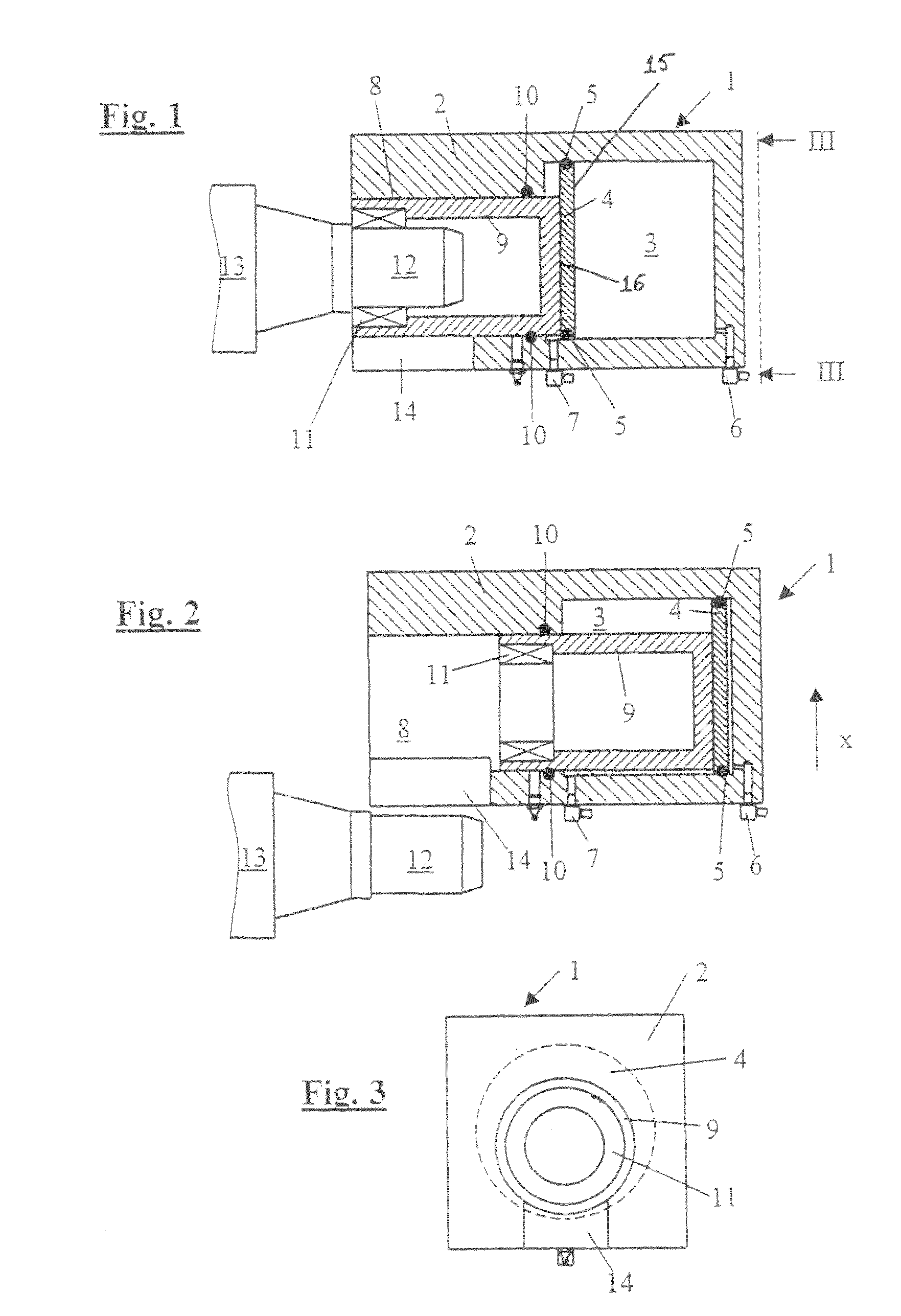
[0026]FIGS. 1 and 2 illustrate a mandrel-locking unit 1 substantially comprising a pressurizing medium cylinder 2. The pressurizing medium cylinder 2 has a pressure chamber 3 into which a piston 4 having a boundary surface 15 can be slid. The piston 4 has on its outer circumference a sealing ring 5 that, as is known, prevents compressed air from one side of the piston 4 from reaching its other side. The compressed air is fed into the pressure chamber by the compressed air inlets 6, 7. The pressurizing medium cyli...


PUM


Abstract

A mandrel-locking unit for a rotary printing machine has a mandrel-mounting element that surrounds print roller mandrels in an inner bearing for mounting a mandrel-supporting surface and into which the mandrel-mounting element can be slid such that the mandrel-supporting surface is released by the sliding movement. The unit has a pressurizing medium cylinder that provides the force required for the sliding movement and a piston, which delimits a pressure chamber of the pressurizing medium cylinder at a boundary surface and which is in contact with the mandrel-mounting element at a connecting point and conveys to the mandrel mounting element the pressure required for the sliding movement. A feature of the unit is that the distance between the boundary surface and the connecting point is smaller than the maximum stroke of the piston in the pressurizing medium cylinder.

Description

CROSS-REFERENCE TO RELATED APPLICATION[0001]This is a nationalization of PCT / EP2004 / 005488 filed 18 May 2004 and published in German.BACKGROUND OF THE INVENTION[0002]1. Field of Invention[0003]The present invention relates to a mandrel-locking unit having a mandrel-mounting element that has a hollow body and that accommodates therein a bearing for mounting a print roller mandrel. A pressurizing medium cylinder has a pressure chamber and a piston located therein for sliding the mandrel-mounting element between a mounting position and a release position.[0004]2. Description of the Prior Art[0005]The processing of different print jobs frequently necessitates the replacement of printing plates. Therefore print rollers are known from the prior art that comprise print roller mandrels whose print roller sleeves, the so-called sleeves—can be pulled off and put back on again. In order to replace the sleeves without having to remove the print roller from the printing machines, the print rolle...

Claims


Application Information

Patent Timeline
IPC IPC(8): B41F13/30B41F13/44B41F13/20B41F13/26B41F27/10
CPCB41F13/20B41F13/26B41P2227/21
Inventor RASCH, GEORGMIESELER, HANS-JOERG
Owner WINDMOELLER & HOELSCHER GMBH
Why Eureka
Try Eureka