
Electromagnet system for a switch

a technology of electromagnetic system and switch, which is applied in the direction of electromagnet, polarised relay, core/yokes, etc., can solve the problems of device heat up, power loss of a few watts, and power consumption in the holding state, so as to achieve minimal cutout power, less space, and avoid interference fields

Inactive Publication Date: 2005-06-14
KLOCKNER-MOELLER GMBH
View PDF10 Cites 3 Cited by
  • Summary
  • Abstract
  • Description
  • Claims
  • Application Information

AI Technical Summary

Benefits of technology

[0021]An advantage of the present invention is that it permits a circuit system (preferably having pulse width modulation) for activating the excitation winding and delivering electric power for the excitation winding to be operated virtually in the stand-by mode.
[0022]The EMC measures may be reduced because in the holding state only the electric power for the idling power of the circuit must be provided. In comparable magnet systems, the power is cyclical in the holding state, whereby interference fields cannot be avoided. The cutout power is minimal. The holding power is low and corresponds to the standby power of the control electronics. The design of the electronics is determined only by its own power consumption. From the point of view of power, the magnetic circuit is designed only for the “close magnet armature” situation. The cutout power should preferably be ensured in the pull-in phase, for example, by charging a capacitor during the pull-in phase. As is the case in comparable systems, the permanent magnet is made of a magnetically hard material, for example, of AlNiCo, rare earth compounds being also utilizable.
[0023]The advantage of the magnet system is in particular that less space is needed for the excitation coil, permitting a more compact design.
[0024]The present invention may be used in general wherever the motion of the magnet armature is convertible into the form of a linear drive.

Problems solved by technology

Power consumption in the holding state has the disadvantage that the device heats up.
Power losses of a few watts are typically expected in the holding state.
For vacuum switchgears, considerably higher power losses may occur.
The use of electronics has not yet resulted in satisfactory improvement.
This method results in the need for generating increasingly narrower pulses in the circuit as power consumption decreases.
As the pulses become narrower, harmonic components appear, which cause problems in electromagnetic shielding and compatibility.

Method used


Image

  • Electromagnet system for a switch
  • Electromagnet system for a switch
  • Electromagnet system for a switch

Examples


Embodiment Construction

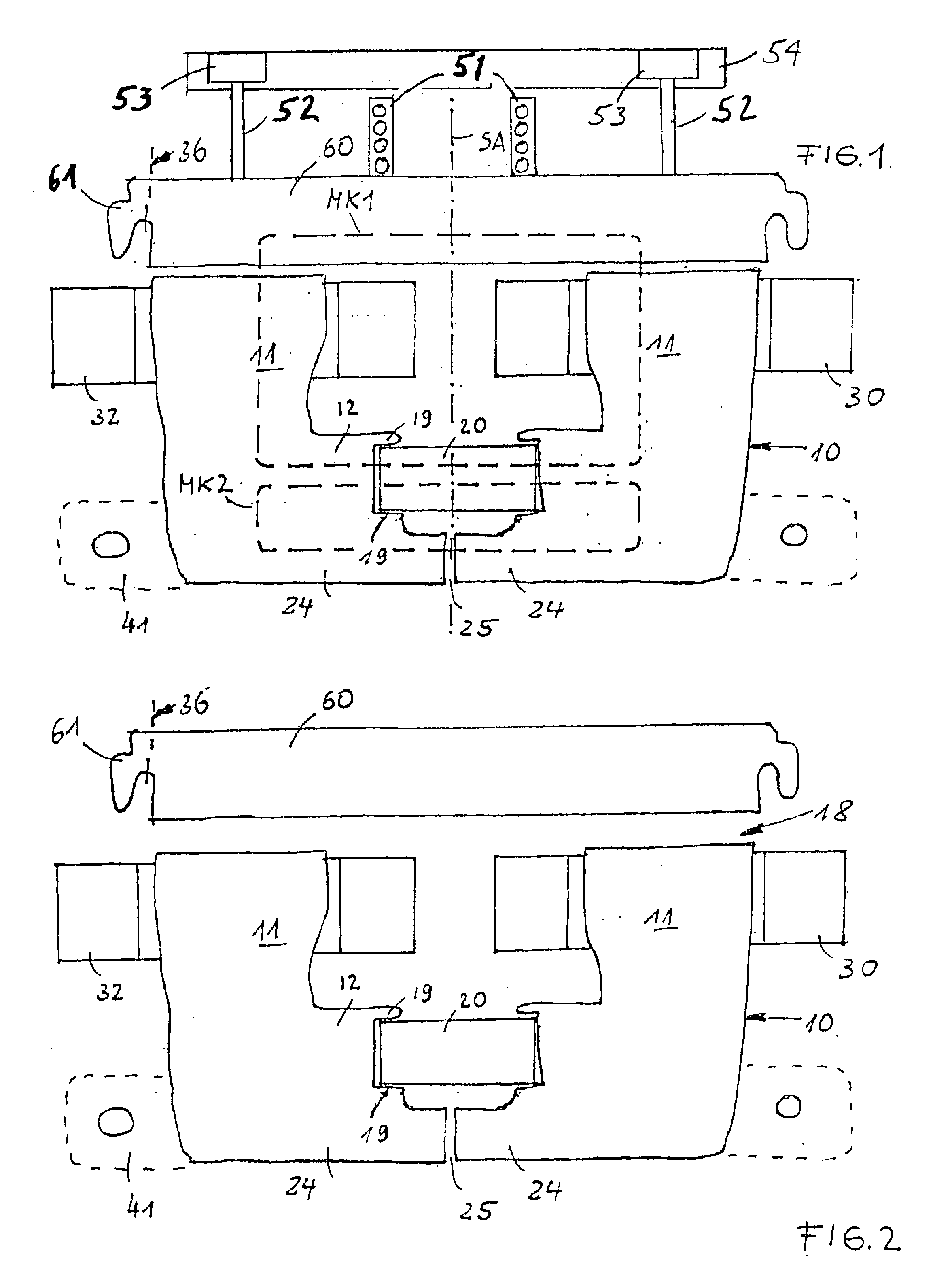
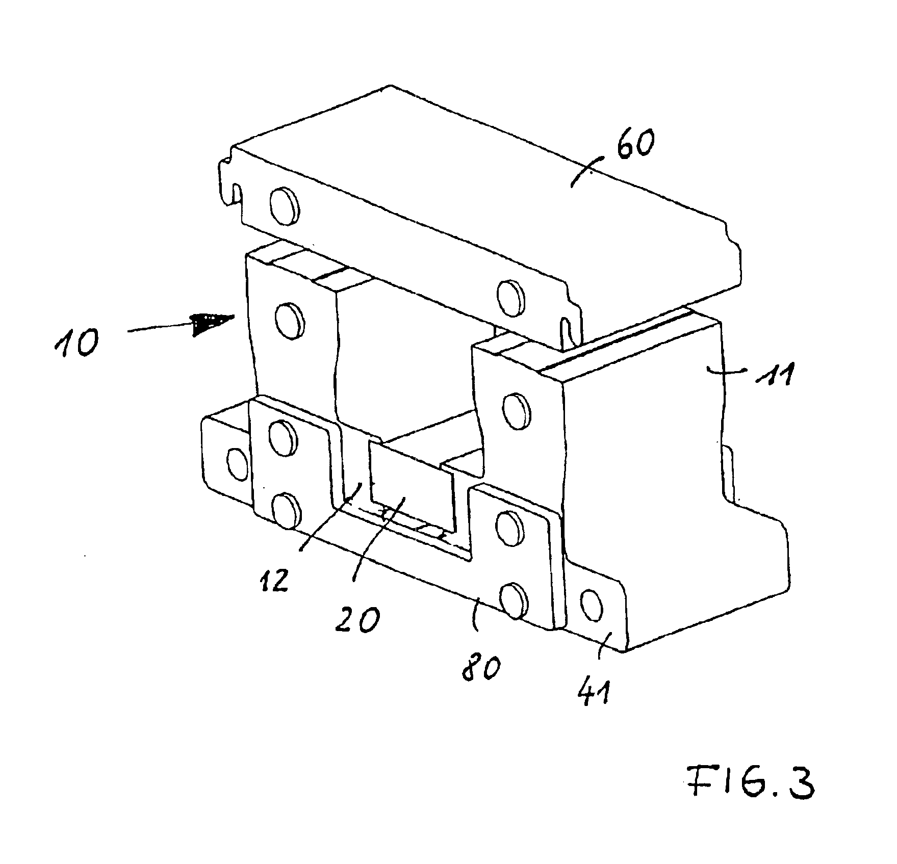
[0029]Magnet yoke 10 has a U shape and has two symmetric halves (in an L shape) with respect to the vertical axis of symmetry SA with longer pole legs 11 and short cross legs 12. The cross legs are facing each other. A permanent magnet 20 is mounted between the cross legs. For this purpose, the ends of the cross legs have projections 19, between which the permanent magnet is clamped during assembly. In contrast to comparable magnet constructions, where expensive laser welding joints are used, this is an elegant and simple construction. FIG. 3 shows the assembly drawing, where it can be seen that the magnet system is made of sheet metal stacks which are riveted through cover plates 80, resulting in mechanical cohesion.

[0030]The free ends of pole legs 11 form a plane as pole faces for magnet armature 60. Magnet armature 60 is made of a plate-shaped body having lateral extensions 61. A restoring force is applied to the magnet armature, which should be preferably linearly movable, by at...


PUM


Abstract

An electromagnet system for a switch includes a main magnetic circuit including a magnet yoke and a magnet armature mechanically linked to a contact apparatus. At least one permanent magnet is disposed in the main magnetic circuit for generating a holding force for the magnet armature. A shunt circuit is provided parallel with the main magnetic circuit so that the permanent magnet is a magnetic energy source for the shunt circuit. The shunt circuit includes pole legs and a yoke arc of the magnet yoke. The magnet armature is capable of contacting the pole legs so as to close the shunt circuit. An excitation winding is provided for each of the pole legs for to generating a pull-in force for the magnet armature. The electromagnet system is magnetically dimensioned such that a minimum magnetomotive force of the excitation windings is sufficient for opening the electromagnet system.

Description

[0001]The present invention relates generally to an electromagnet system for a switch, and in particular to an electromagnet system for a switch contactor, the electromagnet system including a main magnetic circuit formed by a magnet yoke and a magnet armature, and including a shunt circuit which is closable via the magnet armature and is parallel to the main magnetic circuit.BACKGROUND[0002]Electromagnetic switch contactors are usually dimensioned electrically and magnetically so that little electric power is to be applied in the holding state of the magnet armature (e.g., German Patent Application 195 26 038 A1). This is recommended because devices of this type are in the holding state most of their operating time. Power consumption in the holding state has the disadvantage that the device heats up. Power losses of a few watts are typically expected in the holding state. For vacuum switchgears, considerably higher power losses may occur. Considering the fact that contactors or swi...

Claims


Application Information

Patent Timeline
Patent Type & Authority Patents(United States)
IPC IPC(8): H01H47/22H01H51/22H01H50/16H01H50/42H01H71/32H01H71/12
CPCH01H47/226H01H71/321H01H51/22H01H50/42
Inventor LANG, VOLKER
Owner KLOCKNER-MOELLER GMBH
Learn More