Separator plate with periodic surface structures in the nanometer to micrometer range

a technology of periodic surface structure and separator plate, which is applied in the direction of laser beam welding apparatus, fuel cells, electrochemical generators, etc., can solve the problems of negative effect on the service life of separator plates, adversely affecting the function of separator plates to establish low-loss electrical connections, and tending to passivate, so as to achieve greater mechanical stability of metal and compact design of fuel cells

Pending Publication Date: 2021-09-16
REINZ DICHTUNGS
View PDF2 Cites 0 Cited by
  • Summary
  • Abstract
  • Description
  • Claims
  • Application Information

AI Technical Summary

Benefits of technology

[0003]Separator plates can have different functions depending on the field of application. On the one hand, they are used to ensure an electrically conductive connection to an adjoining layer, which may be for example a gas diffusion layer. On the other hand, separator plates are typically used to supply and / or remove reactants and / or reaction products, with a channel structure usually being provided for this purpose. In addition, reaction heat can be conveyed away by means of the separator plates, for example by means of a coolant. For mobile applications, such as in motor vehicles, it may be desired to produce separator plates from metal because the greater mechanical stability of metal compared to other materials allows a more compact design of fuel cells and fuel cell stacks.

Problems solved by technology

However, a problem arises from the fact that metals which are suitable from an economic point of view, and which are sufficiently corrosion-resistant to withstand the aggressive conditions usually prevailing in fuel cells, tend to passivate.
However, a passivation layer leads to a significantly increased electrical contact resistance on a contact surface, thereby adversely affecting, to an extent beyond reasonable, the function of a separator plate to establish a low-loss electrical connection.
Said aggressive reaction conditions also have a negative effect on the service life of the separator plates.
The low repetition rate results in considerable dead times, so that the total energy input is limited and only the surface layer is modified.

Method used


Image

  • Separator plate with periodic surface structures in the nanometer to micrometer range
  • Separator plate with periodic surface structures in the nanometer to micrometer range
  • Separator plate with periodic surface structures in the nanometer to micrometer range

Examples


Embodiment Construction

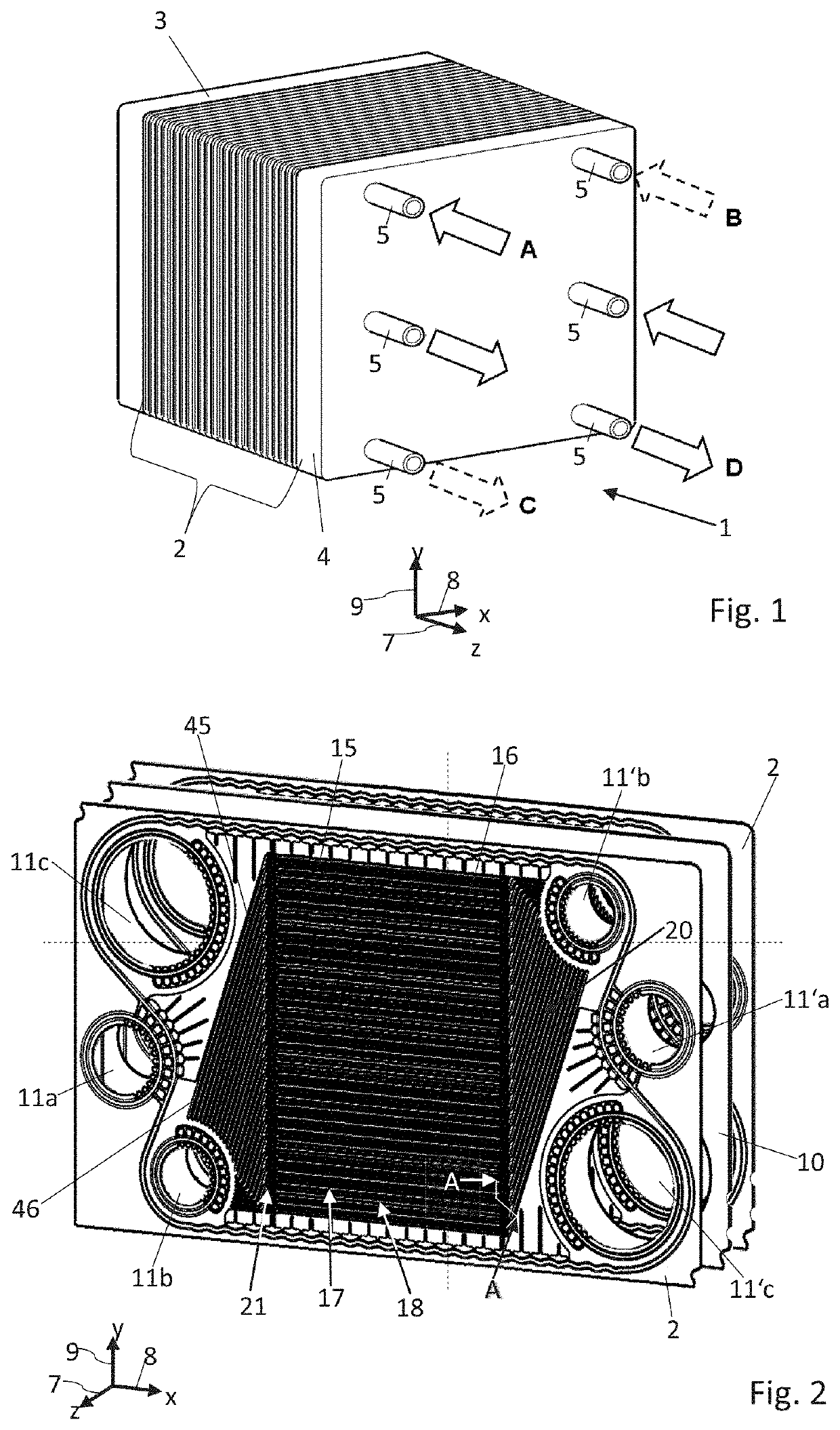
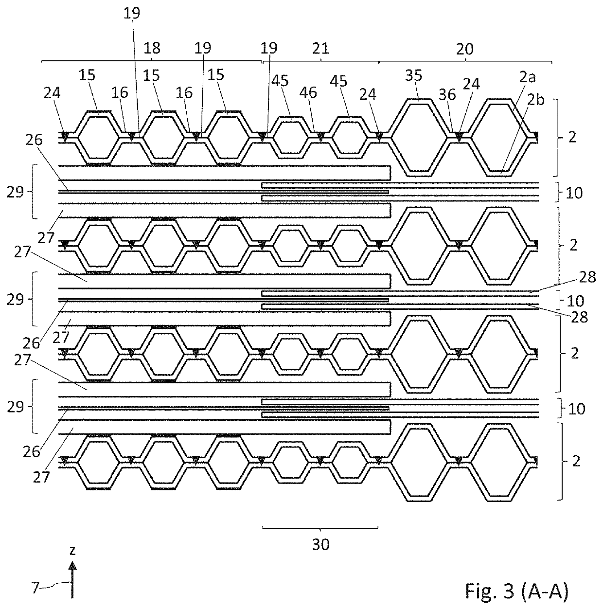
"d_n">[0076]FIG. 1 shows an electrochemical system 1 of the type proposed here, comprising a plurality of structurally identical metal bipolar plates 2 which are arranged in a stack and are stacked along a z-direction 7. The bipolar plates 2 of the stack are clamped between two end plates 3, 4. The z-direction 7 will also be called the stacking direction. The bipolar plates 2 usually each comprise two metal separator plates 2a, 2b which are connected to one another (see for example FIGS. 2 and 3). In the present example, the system 1 is a fuel cell stack. Each two adjacent bipolar plates 2 of the stack therefore enclose an electrochemical cell therebetween, which serves for example to convert chemical energy into electrical energy. The electrochemical cells usually each have a membrane electrode assembly (MEA) 10 (see for example FIGS. 2 and 3). The MEA typically contains in each case at least one membrane, for example an electrolyte membrane. Furthermore, a gas diffusion layer (GDL...


PUM

PropertyMeasurementUnit
widthaaaaaaaaaa
widthaaaaaaaaaa
diameteraaaaaaaaaa

Abstract

The present disclosure relates to a separator plate for an electrochemical system, wherein the separator plate has, at least in some regions, periodic surface structures with a mean spatial period of less than 10 μm. The disclosure additionally relates to a method for producing a separator plate for an electrochemical system, comprising the steps: providing a separator plate; irradiating the separator plate by means of a pulsed laser, wherein a pulse duration of the laser pulses is less than 1 ns; and creating periodic surface structures on the separator plate by way of the laser radiation.

Description

CROSS-REFERENCE TO RELATED APPLICATION[0001]The present application claims priority to German Patent Application No. 10 2020 202 999.7, entitled “SEPARATOR PLATE WITH PERIODIC SURFACE STRUCTURES IN THE NANOMETER TO MICROMETER RANGE,” and filed on Mar. 10, 2020. The entire contents of the above-listed application are hereby incorporated by reference for all purposes.TECHNICAL FIELD[0002]The present disclosure relates to a separator plate for an electrochemical system and to a method for producing such a separator plate. The electrochemical system may be a fuel cell system, an electrochemical compressor, an electrolyser or a redox flow battery.BACKGROUND AND SUMMARY[0003]Separator plates can have different functions depending on the field of application. On the one hand, they are used to ensure an electrically conductive connection to an adjoining layer, which may be for example a gas diffusion layer. On the other hand, separator plates are typically used to supply and / or remove react...

Claims


Application Information

Patent Timeline
Patent Type & Authority Applications(United States)
IPC IPC(8): H01M8/026H01M8/18B23K26/0622
CPCH01M8/026B23K2101/36B23K26/0624H01M8/188H01M8/0202H01M8/0258B23K26/352B23K26/355B23K26/3584Y02E60/50H01M8/0228Y02P70/50
Inventor GAUGLER, BERNDGRAFL, DIETERWENZEL, STEPHAN
Owner REINZ DICHTUNGS
Why Eureka
Try Eureka