Tire with quadrangular studs
- Summary
- Abstract
- Description
- Claims
- Application Information
AI Technical Summary
Benefits of technology
Problems solved by technology
Method used
Image

Examples
first embodiment
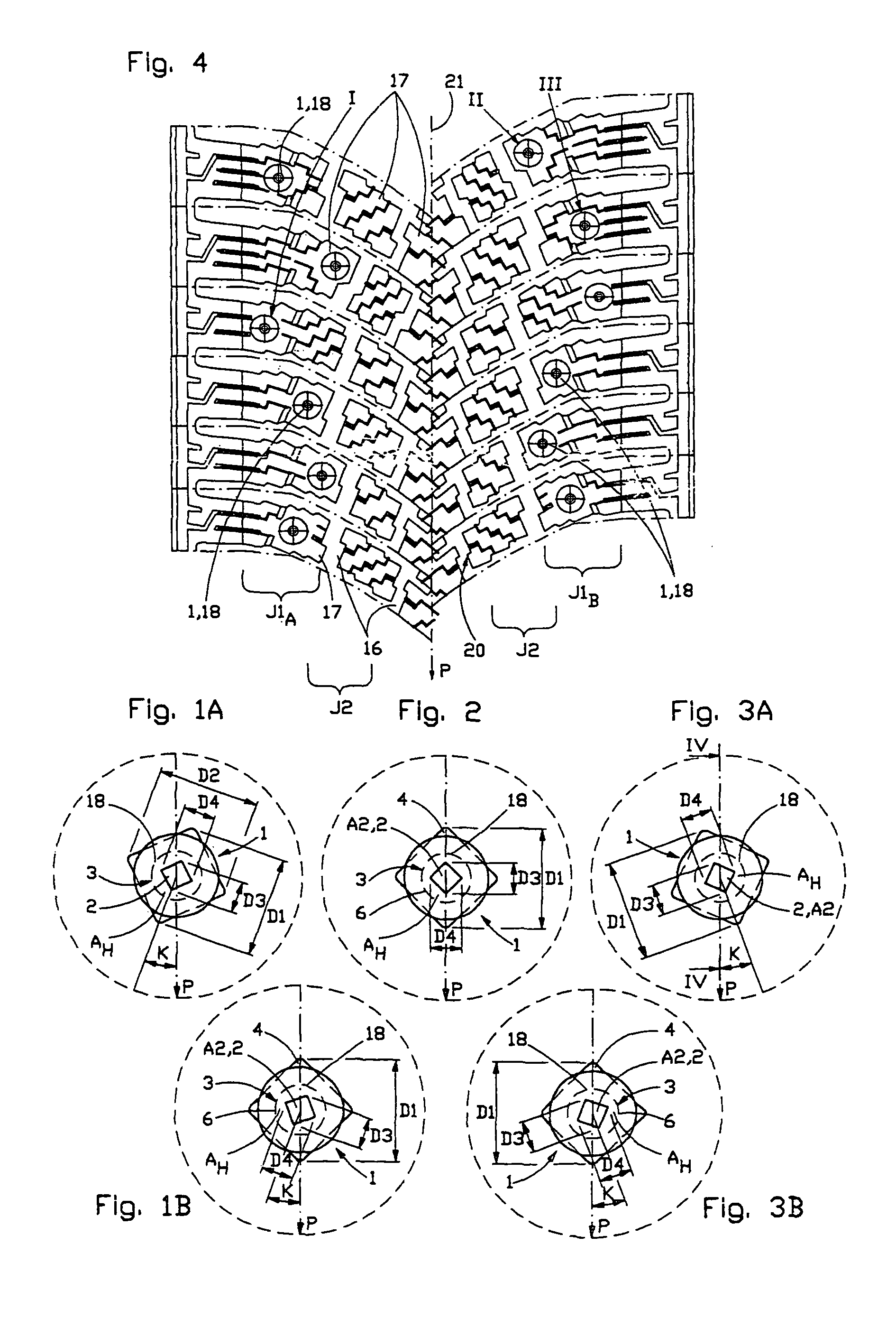
[0061]According to a stud installation method, all anti-slip studs used in a given tire are, with regards to the directions or positions of the diagonal dimensions D3, D4 of the hard cermet piece relative to the diagonal dimensions D1, D2 of the bottom flange 4, of the same type. In some implementations, for example, all the studs are of a type where at least one of the diagonal dimensions D3 or D4 of the hard cermet piece is parallel with at least one of the diagonal dimensions D1 or D2 of the bottom flange. More specifically, in certain implementations, both of the diagonal dimensions D3 and D4 of the hard cermet piece are parallel with the corresponding diagonal dimensions D1 and D2 of the bottom flange.
[0062]In the first embodiment, the control elements of the installation machine (not shown) are always arranged in such a position, with respect to the tire tread under operation, that the studs 1 are set in a desired orientation. The installation method is apparent from FIGS. 1A,...
second embodiment
[0063]According to a stud installation method, the anti-slip studs used in a given tire are, with regards to the directions or positions of the diagonal dimensions D3, D4 of the hard cermet piece relative to the diagonal dimensions D1, D2 of the bottom flange 4, of at least two different types. In at least one of the two types, the diagonal dimension D3 and / or D4 of the hard cermet piece forms a toe-out angle K of a predetermined size with the diagonal dimension D1 and / or D2 of the bottom flange.
[0064]In the second embodiment, the control elements of the installation machine can be arranged in a standard position based on the angle differences between the diagonals of the hard cermet piece and the diagonals of the bottom flange and the corresponding desired toe-out angles K in a finished studded tire. Based on the various regions of the tire tread in which a stud is desirably installed, the desired orientation of the hard cermet piece is obtained by changing the type of the studs to...
PUM
 Abstract
Description
Claims
Application Information