
Apparatus and method for treating a regurgitant valve

a heart valve and appendix technology, applied in the field of appendix and method for treating and improving the function of dysfunctional heart valves, can solve the problems of complex and time-consuming repair or reconstruction of leaflets, defective or damaged heart valves from degeneration, etc., to facilitate the positioning of the occluding member and reduce the risk of regurgitation

Active Publication Date: 2011-03-08
THE CLEVELAND CLINIC FOUND
View PDF18 Cites 119 Cited by
  • Summary
  • Abstract
  • Description
  • Claims
  • Application Information

AI Technical Summary

Benefits of technology

The present invention provides an apparatus and method for treating regurgitation of blood through a diseased heart valve. The apparatus includes an occluding member attached to a suspending wire, which is designed to be positioned within the heart valve to mitigate regurgitation of blood. The occluding member contacts at least one surface of the heart valve leaflet to reduce the size of the regurgitant jet. The method involves positioning the apparatus in the heart chamber containing the heart valve and using a balloon to determine the size and shape of the heart valve. The size and shape of the occluding member is selected to correspond to the size and shape of the diseased heart valve. The apparatus is introduced into the patient's body and positioned in the heart chamber where the heart valve is located. The technical effect of the invention is to provide a minimally invasive treatment for heart valve regurgitation that can be performed in a safe and effective manner.

Problems solved by technology

A heart valve may become defective or damaged from degeneration caused by congenital malformation, disease, aging, and the like.
When the valve becomes defective or damaged, the leaflets may not function properly to effectively prevent blood flow through the valve when appropriate.
The repair or reconstruction of the leaflets can be complicated and time consuming.

Method used


Image

  • Apparatus and method for treating a regurgitant valve
  • Apparatus and method for treating a regurgitant valve
  • Apparatus and method for treating a regurgitant valve

Examples


Embodiment Construction

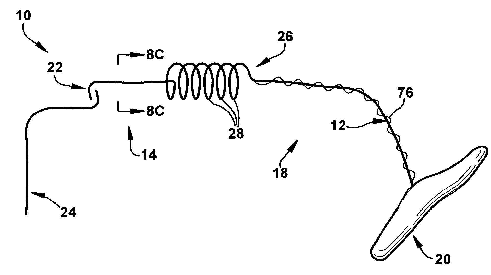
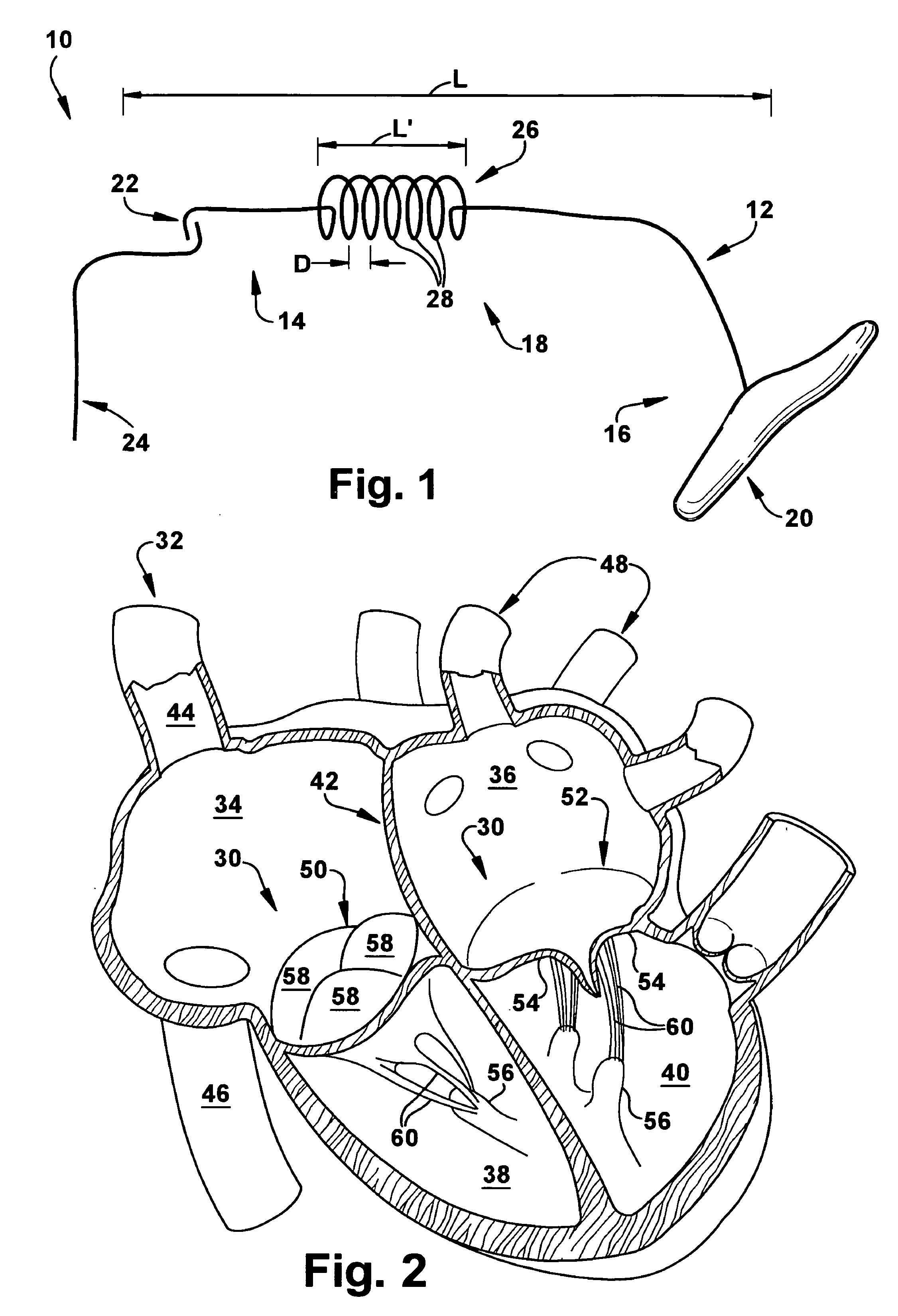
[0049]The present invention relates to an apparatus and method for treating and improving the function of dysfunctional heart valves. More particularly, the present invention relates to an apparatus and method that passively assists in closing the native leaflets to improve valve function of a regurgitant valve. As representative of the present invention, FIG. 1 illustrates an apparatus 10 for treating regurgitation of blood through a diseased heart valve 30 (FIG. 2) having at least two leaflets.

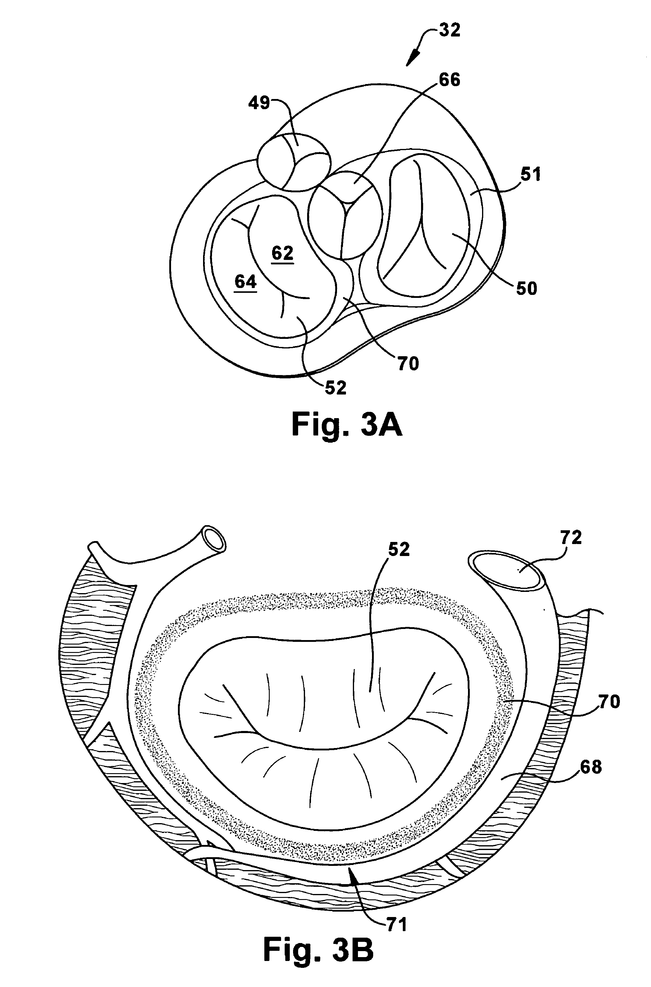
[0050]FIG. 2 schematically illustrates a human heart 32 which includes four chambers: the right and left atria 34 and 36, respectively, and the right and left ventricles 38 and 40, respectively. The right and left atria 34 and 36 are divided by the interatrial septum 42. The thin-walled right atrium 34 receives deoxygenated blood from the superior vena cava 44, the inferior vena cava 46, and from the coronary sinus 68 (FIG. 3B). The thin-walled left atrium 36 (FIG. 2) receives oxygenated blo...


PUM


Abstract

An apparatus for treating regurgitation of blood through a diseased heart valve having at least two leaflets includes an occluding member configured to be positioned within the diseased heart valve so that at least a portion of the occluding member is positioned adjacent to one of the at least two leaflets. The at least one portion of the occluding member contacts at least one surface of the at least one leaflet. The occluding member is dimensioned so that the at least one leaflet abuts the at least one surface of the occluding member. The apparatus further includes a suspending wire operatively attached to the occluding member and configured to facilitate positioning of the occluding member within the heart valve. The suspending wire includes an anchoring portion having a coiled shape. The anchoring portion is configured to secure the suspending wire to at least one of a blood vessel and a heart wall surrounding a heart chamber.

Description

RELATED APPLICATION[0001]This application claims priority from U.S. Provisional Application No. 60 / 750,580, filed Dec. 15, 2005, the subject matter of which is incorporated here by reference.TECHNICAL FIELD[0002]The present invention relates to an apparatus and method for treating and improving the function of dysfunctional heart valves. More particularly, the present invention relates to an apparatus and method that passively assists in closing the native valve leaflets to improve valve function of a regurgitant heart valve.BACKGROUND OF THE INVENTION[0003]A heart valve may become defective or damaged from degeneration caused by congenital malformation, disease, aging, and the like. When the valve becomes defective or damaged, the leaflets may not function properly to effectively prevent blood flow through the valve when appropriate. For example, when a mitral valve functions properly, the mitral valve prevents regurgitation of blood from the left ventricle into the left atrium whe...

Claims


Application Information

Patent Timeline
Patent Type & Authority Patents(United States)
IPC IPC(8): A61F2/24
CPCA61B17/00234A61B17/0401A61F2/246A61B2017/00575A61B2017/00588A61B2017/00592A61F2/2496A61B2017/00606A61B2017/00615A61B2017/0417A61B2017/0443A61B2017/00597
Inventor KAPADIA, SAMIRYADAV, JAY
Owner THE CLEVELAND CLINIC FOUND
Learn More