
System and method for deploying virtual machines in a computing environment

a computing environment and virtual machine technology, applied in the field of system and method for deploying virtual machines in the computing environment, can solve the problems of lack of logic for generating vm-specific operations, inability to detect or resolve referenced techniques, and no known products

Inactive Publication Date: 2011-03-08
IBM CORP
View PDF9 Cites 71 Cited by
  • Summary
  • Abstract
  • Description
  • Claims
  • Application Information

AI Technical Summary

Benefits of technology

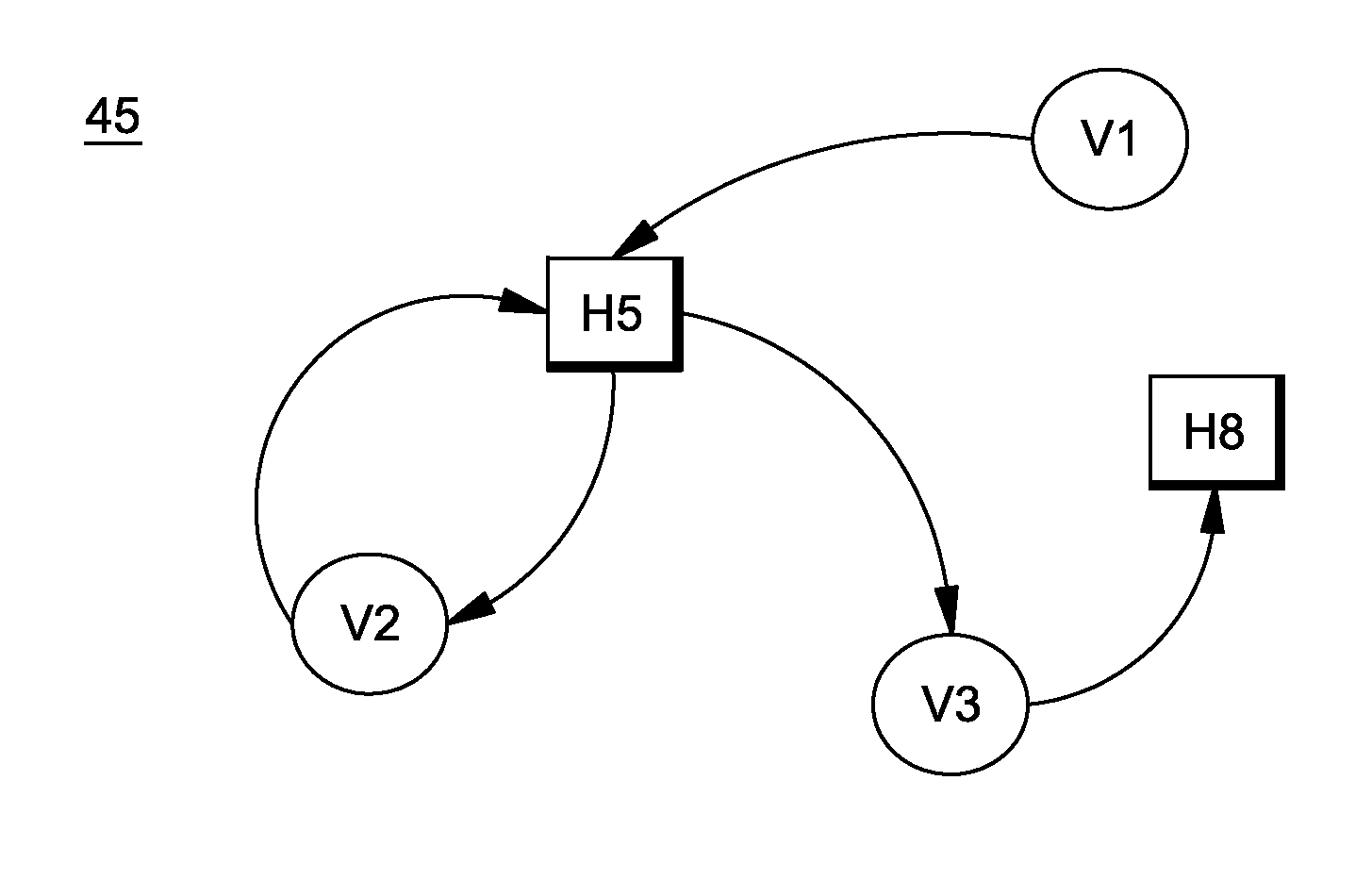
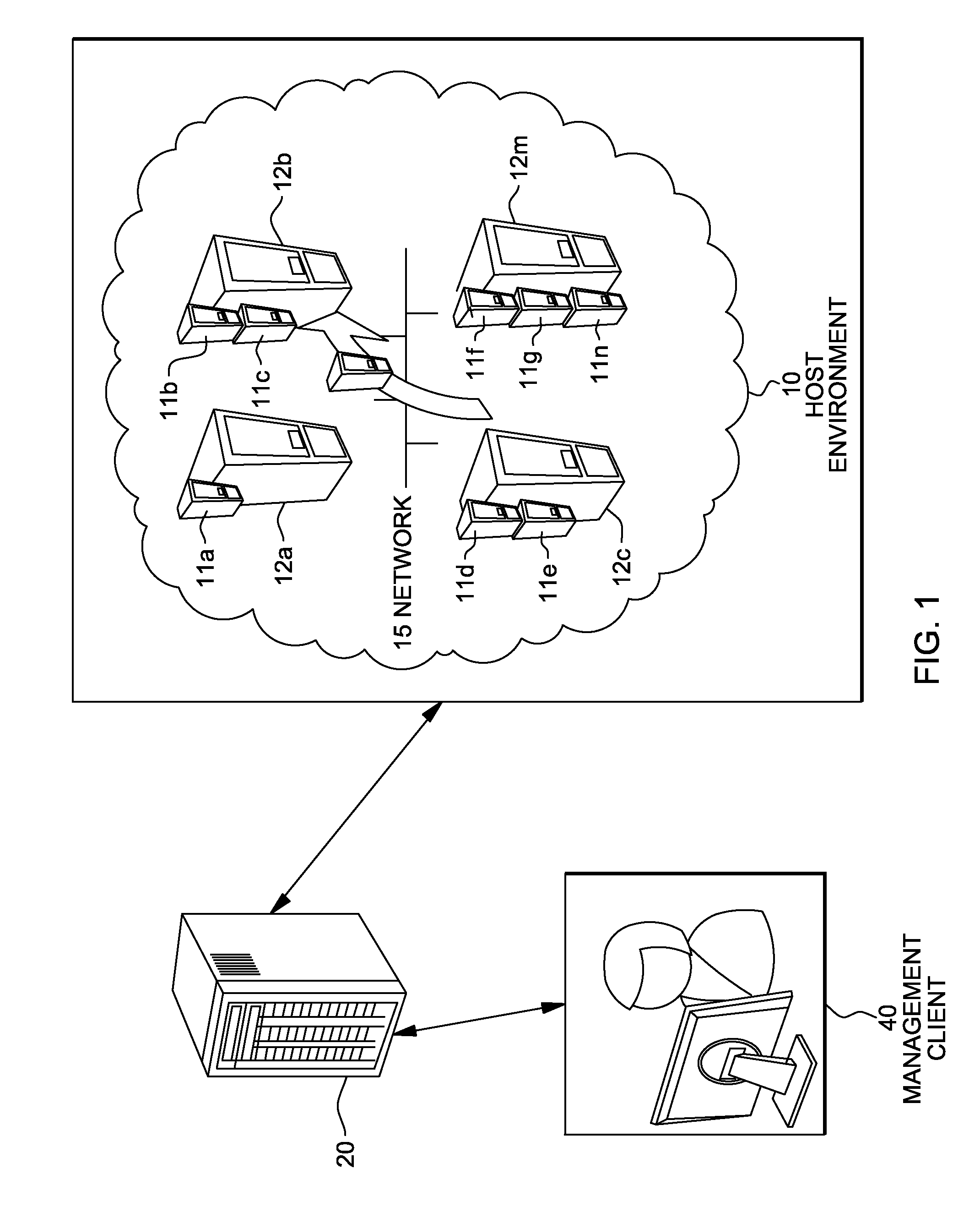
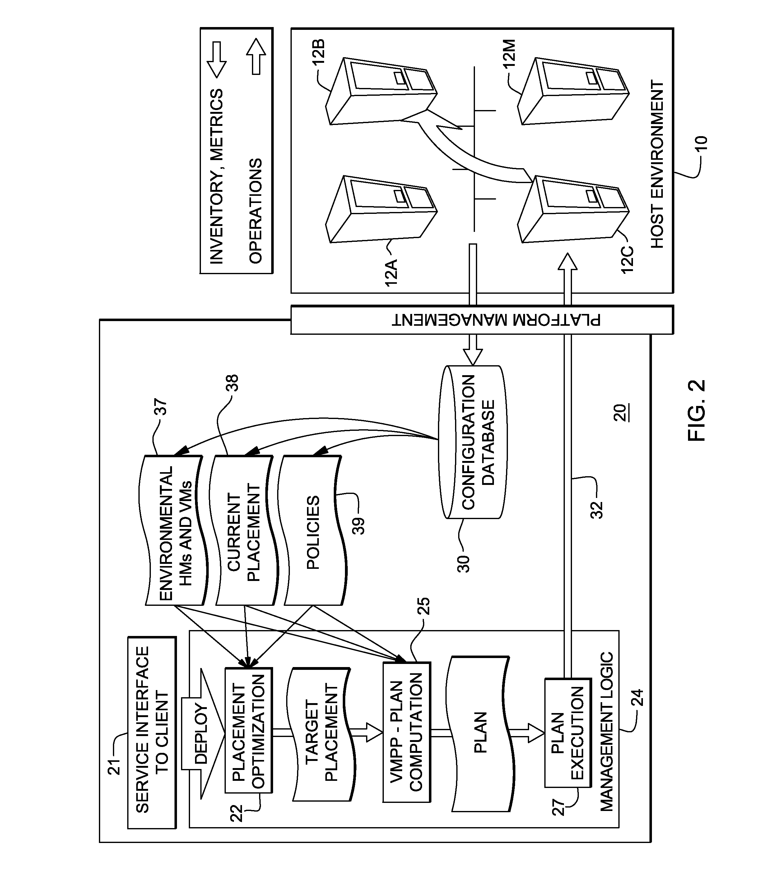
The present invention is a system and method for automatically generating a plan for changing the placement of virtual machines (VMs) in a computing environment. The system uses a graph-based model to determine the optimal placement of VMs based on their current placement, the policies and resource constraints associated with them, and the host machines on which they are placed. The system breaks migration cycles by "abusing" VMs and removing them from their current host to make room for other VMs. The resulting plan adheres to the policies and resource constraints and ensures that each VM is placed at its desired target host. The system includes a computing device that provides the current placement function and a modifiable copy of it, as well as a target placement function. The system also uses a technique of graph pruning to iteratively generate the plan and ensure that each temporary state in the plan does not violate any policy or resource constraint. The technical effects of the invention include automated placement planning for VMs in a computing environment, improved resource utilization, and reduced migration cycles.

Problems solved by technology

However, none of the existing products is known to include a technology that uses similar concepts to those described in the present invention for automatic generation of a plan for changing the current placement of virtual machines in a datacenter of distributed computing resources into a given desired (target) placement.
First, the referenced technique is not based on a model of VMs, so it lacks the logic for generating VM-specific operations, such as “relocate”, “suspend”, etc.
Also, being ignorant of migrations / relocations (that are not part of the service model), the referenced technique does not detect or resolve “migration cycles”.
These trivial solutions can easily result in illegal temporary states, however, such as overloading a host beyond its resource capacity, or placing multiple VMs on the same host despite a policy that forbids them from sharing a host.
Thus, while the concepts of automated planning, resource allocation, goal-driven planning (to reach from state A to state B) and ordering steps according to dependencies have been studied, there does not appear to be any prior art describing a solution for building a model for VM placement that facilitates the generation of an appropriate placement plan that avoids violating policies / constraints, and, additionally that accounts for migration cycles.
Moreover, neither the patent nor non-patent literature addresses observing migration cycles caused by policies, much less the concept of abusing a VM for breaking migration cycles.

Method used


Image

  • System and method for deploying virtual machines in a computing environment
  • System and method for deploying virtual machines in a computing environment
  • System and method for deploying virtual machines in a computing environment

Examples


first embodiment

[0133]FIG. 7A depicts an example of an abuse strategy of a first embodiment that works by un-placing a VM, that is, making it release its allocated resources at its current host without being relocated to another host. The example implementation of select_abuse( ) 91 function in FIG. 7A implements this strategy. The function takes a single parameter SV which is the set of candidate VMs to choose from. In step 1 of the select_abuse( ) 91 function in FIG. 7A, the function tries to first select a candidate VM v that holds resources on a host (i.e., mcp(v)≠@) and that can tolerate suspension of its operation (i.e., liveMigrate(v)=FALSE). If it finds such a VM of the select_abuse( ) 91 function in FIG. 7A, (step 2), that VM is returned (step 2.1 of the select_abuse( ) 91 function in FIG. 7A). Otherwise, it tries in step 3 of the select_abuse( ) 91 function in FIG. 7A to find any VM that holds resources. If such a VM is found (step 4 of the select_abuse 91 function in FIG. 7A), it is retu...

second embodiment

[0134]FIG. 7B presents yet another example of an abuse strategy of a by relocating VMs to HMs hosts) outside the cycle, so that the abused VM's operation does not have to be temporarily suspended. The hosts are picked out of a predefined set PH. The set PH could be a predefined dedicated pool of backup servers that are reserved for such use, or it could be a set that was dynamically constructed during the operation of the algorithm, e.g., by adding every HM h with in(h)==0 to PH (step 7 of the preparation sequence described supra, and step 3.3.3 of the main portion of algorithm 50 in FIG. 3). In any case, PH should not contain hosts that part of the graph at the time the abuse operation is invoked, so that using its hosts for abused VMs may not generate additional migration cycles. Note that this abuse strategy will try to place each candidate VM at a HM out of PH, so it is more costly in terms of time complexity compared to the un-place strategy. However, if migration cycles are ex...


PUM


Abstract

A system and method for planning placement of virtual machines VMs in a computing environment comprising a set of hosting machines HM. The method includes constructing a bipartite directed graph-based model that represents both a current and a target placement states, both including virtual machine nodes v in VM and nodes h in HM. Using a technique of graph pruning, the method iteratively generates a plan for achieving a desired target placement starting from the current placement without temporarily violating any policy or resource constraint. The application of the pruning algorithm to VM deployment automation necessarily defines a new model. The methodology employed safely manages concurrent changes in a datacenter, so that the environment can adjust faster to changing constraints. Furthermore, the present invention allows detection of migration cycles, caused by deadlocked combinations of capacity and policy constraints, and resolving them.

Description

FIELD OF THE INVENTION[0001]The present disclosure relates generally to calculating and deploying of resource-consuming virtual entities, e.g., virtual machines, in computing environments, e.g., a datacenter or a “cloud” of distributed computing resources, and more particularly, to a system and method for dynamic managing placement (i.e., assignment of physical hosts and resources to VMs) of virtual machines (VMs) in computing environments from a first placement state into a given desired (target) placement state in a manner that adheres to a set of constraints.BACKGROUND OF THE INVENTION[0002]Solutions for the automated optimizing and transitioning of placements of multiple virtual machines (VMs), e.g., Xen® VMs (www.Xen.org) in a computing environment have only recently begun to be addressed by the industry, Current VMware® virtualization software products, such as Virtualization Infrastructure (VI) provide technology for enabling automated VM placement. However, none of the exist...

Claims


Application Information

Patent Timeline
Patent Type & Authority Patents(United States)
IPC IPC(8): G06F15/173G06F9/455G06F9/46G06F1/00
CPCG06F9/4856G06F9/45558G06F2009/4557
Inventor HADAD, EREZMOATTI, YOSEF
Owner IBM CORP
Learn More