
Vacuum actuated valve for high capacity storage and delivery systems

a vacuum-actuated valve and high-capacity storage technology, applied in the direction of fluid pressure control, container discharging methods, instruments, etc., can solve the problem of inability to handle cylinder fill pressures greater than 600 psig, affecting and compromising the purity of the gas delivered from the cylinder

Active Publication Date: 2011-03-15
PRAXAIR TECH INC
View PDF25 Cites 92 Cited by
  • Summary
  • Abstract
  • Description
  • Claims
  • Application Information

AI Technical Summary

Benefits of technology

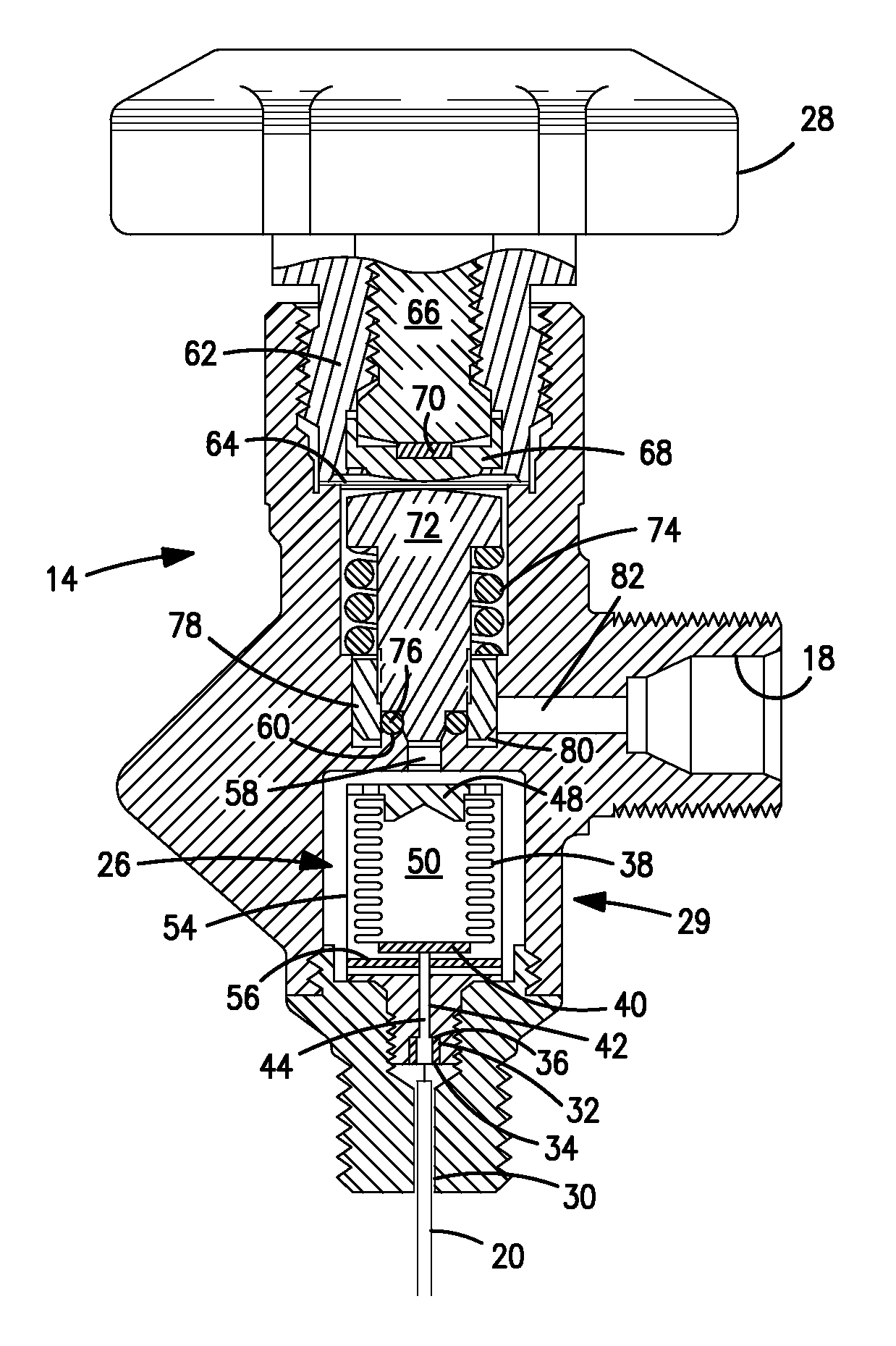
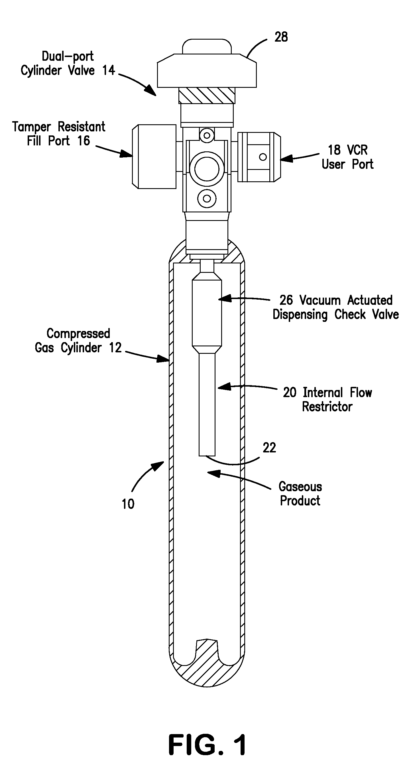
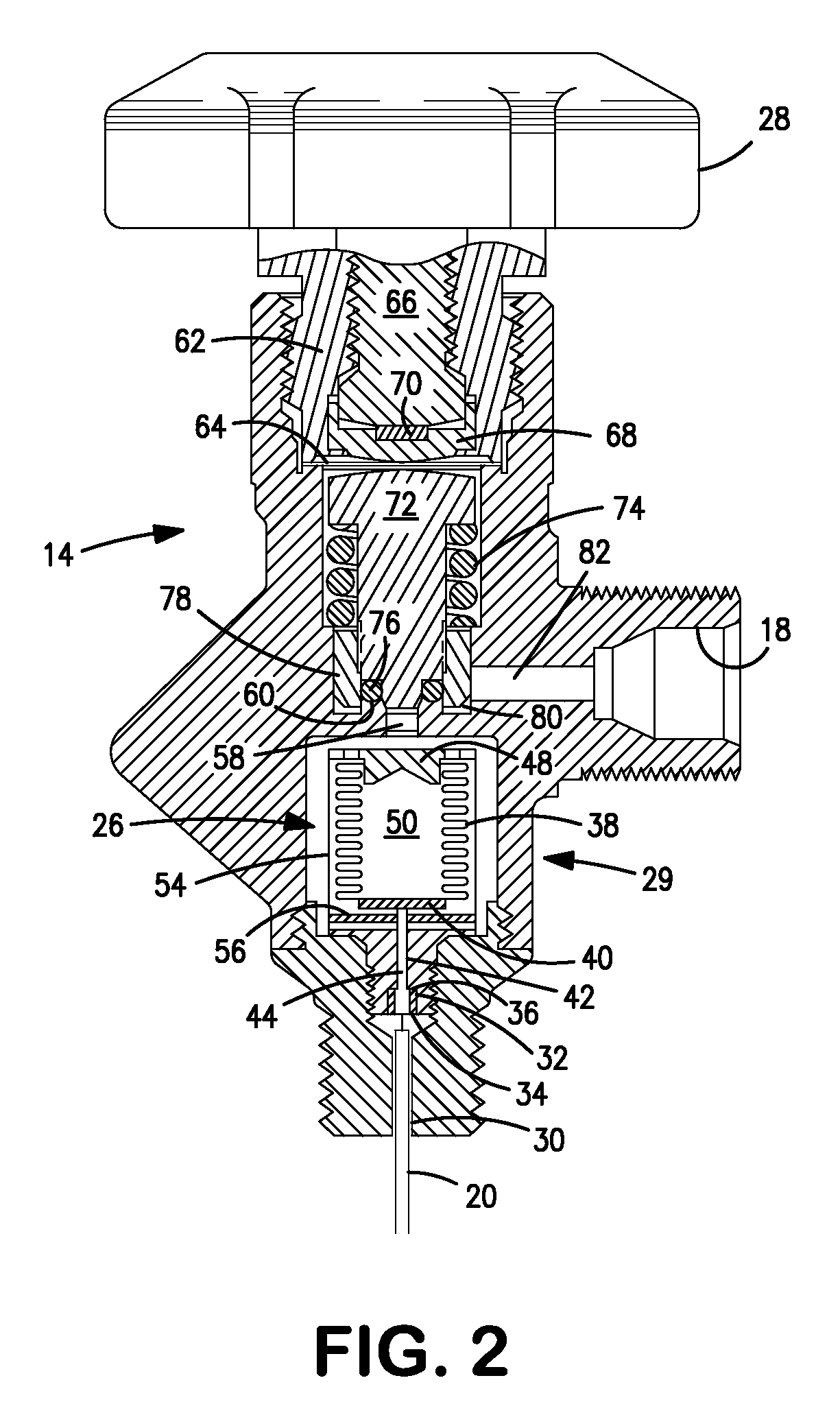
The invention provides a vacuum actuated check valve for delivering fluid from a pressurized source to a processing tool. The check valve has a valve base with a pin and a spring bushing that can move to control fluid flow. A bellows chamber is connected to the valve base and can expand when there is a vacuum to force the spring bushing away from the valve base and allow fluid flow. The invention also includes a system for controlling the discharge of pressurized fluids from a tank, and a cylinder and valve assembly for controlling fluid flow.

Problems solved by technology

Due to their extreme toxicity and high vapor pressure, their use, transportation and storage raise significant safety concerns for the semiconductor industry.
There are certain limitations associated with the SDS technology, and they include: 1) the adsorbent material has a finite loading capacity thereby limiting the amount of product available in a given size cylinder; 2) the desorption process can be initiated by exposing the cylinder package to heat, thereby causing the cylinders to reach and deliver gases at atmospheric and super-atmospheric pressures when the cylinder is exposed to temperatures greater than 70° F., which are common in many cylinder warehouse locations and within the ion implant tool; 3) the purity of the gas delivered from the cylinder can be compromised due to adsorption / desorption of the other materials / gases on the adsorbent material; 4) cylinder percent utilization is highly influenced by the depth of vacuum applied to the package, i.e. cylinders are often returned with appreciable product left in the package; and 5) adsorbent attrition can lead to particulate contamination in the gas delivery system.
The drawbacks associated with the related art storage and delivery systems is that they are unable to handle cylinder fill pressures greater than 600 psig or otherwise would require two devices in series.
Specifically, the related art systems cannot work at cylinder pressures greater than 600 psig due to pin / poppet design of the dispensing valve.
Another disadvantage in the present systems is that they cannot accommodate a higher capacity of fluid product and, therefore, require frequent replacement of the cylinder package.
In turn this leads to frequent change out of the product cylinder and increased down time for the semiconductor manufacturer.

Method used


Image

  • Vacuum actuated valve for high capacity storage and delivery systems
  • Vacuum actuated valve for high capacity storage and delivery systems
  • Vacuum actuated valve for high capacity storage and delivery systems

Examples


example 1

[0055]A conventional cylinder was filled with boron trifluoride at three separate fill pressures. The first was 100 psig, the second 600 psig, and the third 1300 psig. A vacuum was applied at the outlet of the cylinder outlet port, and a flow rate of 2 sccm was maintained by the mass flow controller downstream of the outlet. The valve actuation pressure profile was then observed for a period of two hours. As shown in FIG. 5 at a fill pressure of 1200 psig, the actuation pressure required to open the cylinder permitting a 2 sccm flow of gas was 250±20 torr. At a cylinder fill pressure of 600 psig, an actuation pressure of 400±20 torr was required to open the valve allowing for a 2 sccm flow rate. Finally, at a fill pressure of 100 psig, the actuation or delivery pressure for a 2 sccm flow rate was 530±20 torr. Hence, as the cylinder fill pressure decreases due to consumption of the gas, the actuation pressure increases. FIG. 5 demonstrates that the o-ring seal of the present inventio...

example 2

[0056]A cylinder containing the modified vacuum actuated check valve of the present invention was tested following the same protocol as described in the comparative example above except that the flow rate was increased to 5 sccm. As shown, in FIG. 6, the actuation pressure for the various inlet pressures of the new design appears to stabilize at about 100 seconds. This is quite important because the most critical and time consuming manufacturing operation during the assembly of every vacuum actuated check valve is referred to as “setting the actuation pressure.” In terms of production yield this operation is the major bottleneck in terms of manufacturing valves. If a valve stabilizes (at a flow rate of 5 sccm) in 100 seconds it indicates this specific manufacturing step or process referred to as “setting the actuation pressure” can be performed in 100 seconds.


PUM


Abstract

The invention relates to a re-configured valve design to accommodate a high volume of product in the delivery system and the dispensation of product upon the application of a predetermined vacuum condition on the downstream side of the valve.

Description

BACKGROUND OF THE INVENTION[0001]1. Field of the Invention[0002]The present invention relates to a high pressure storage and delivery system having a modified vacuum actuated valve to prevent the hazardous discharge of fluid from a vessel such as a pressurized cylinder or tank. More specifically, the invention relates to a re-configured valve design to accommodate a high volume of product in the delivery system and the dispensation of product upon the application of a predetermined vacuum condition on the downstream side of the valve.[0003]2. Description of Related Art[0004]Industrial processing and manufacturing applications require the use of highly toxic fluids. The manufacture of semiconductor materials represents one such application wherein the safe storage and handling of highly toxic hydridic or halidic gases becomes necessary. Examples of such gases include silane, germane, ammonia, phosphine, arsine, stibine, hydrogen sulfide, hydrogen selenide, hydrogen telluride, phospho...

Claims


Application Information

Patent Timeline
Patent Type & Authority Patents(United States)
IPC IPC(8): F16K31/126
CPCF16K1/305F17C13/04F16K1/307Y10S137/907F17C2201/0104F17C2201/032F17C2201/058F17C2205/0323F17C2205/0338F17C2205/035F17C2205/0391F17C2223/0153F17C2225/0123F17C2260/036F17C2270/0518Y10S137/906Y10T137/7781Y10T137/7036Y10T137/87917Y10T137/7897Y10T137/7821
Inventor CAMPEAU, SERGE
Owner PRAXAIR TECH INC
Learn More