Self-supporting unitary feed assembly

a unitary feed and assembly technology, applied in the direction of antenna details, antennas, electrical equipment, etc., can solve the problems of significant return loss sources, impedance discontinuities, and degrade electrical performan

Inactive Publication Date: 2011-03-15
COMMSCOPE TECH LLC
View PDF26 Cites 145 Cited by
  • Summary
  • Abstract
  • Description
  • Claims
  • Application Information

AI Technical Summary

Benefits of technology

[0032]An impedance transformer 22, as best shown in FIGS. 4 and 5, may be formed in the proximal end 12 of the waveguide portion 8 to minimize an impedance mismatch between the feed assembly and the further path of RF signals. The proximal end 12 may also be formed as a transition element, for example between a circular and rectangular waveguide or other proprietary interface with the receiver, transmitter or transceiver equipment.
[0040]From the foregoing, it will be apparent that the present invention brings to the art a feed assembly 1 with improved electrical performance, improved structural integrity and significant manufacturing cost efficiencies. A feed assembly according to the invention is a strong, lightweight and permanently environmentally sealed component that may be repeatedly cost efficiently manufactured with a very high level of precision.

Problems solved by technology

The interfaces between the environmental seal(s), dielectric block, waveguide, sub reflector and any adhesives or mechanical interlocks used to secure the components together create impedance discontinuities that are significant sources of return loss.
However, a slight taper along at least the waveguide inner diameter, to improve injection molding mold separation, degrades the electrical performance.
Also, the thickness of the dielectric along the cone and waveguide portions is a trade off between strength and an impedance discontinuity that is difficult to match for, without adding an additional impedance matching element.

Method used


Image

  • Self-supporting unitary feed assembly
  • Self-supporting unitary feed assembly
  • Self-supporting unitary feed assembly

Examples


Embodiment Construction

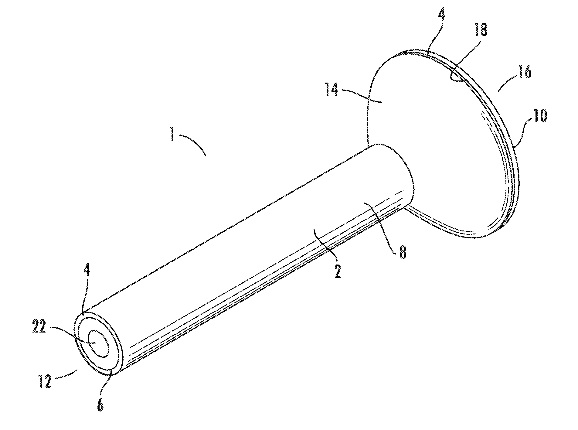
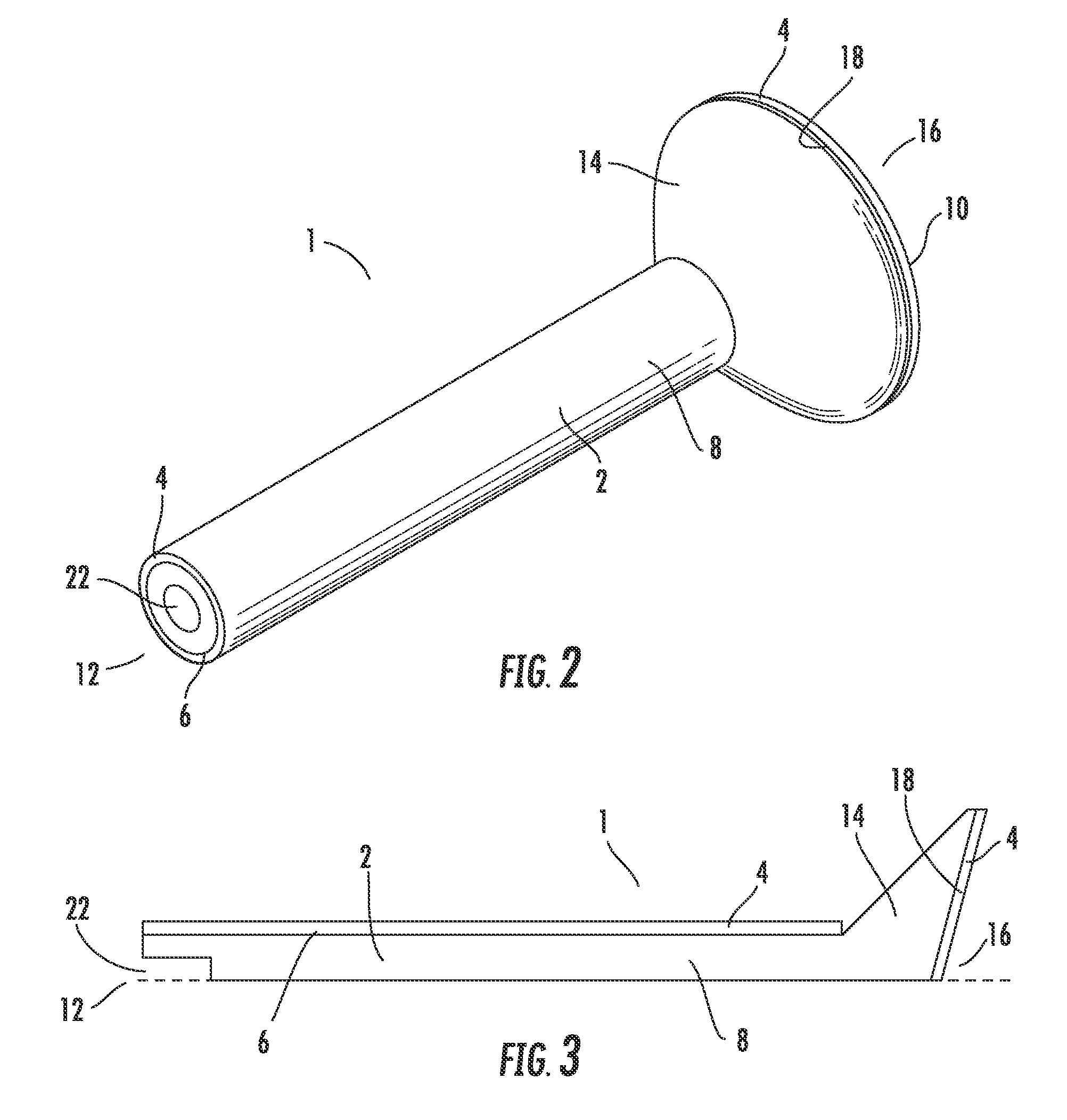
[0026]A circular type waveguide may be selected as the feeder line of a feed assembly, to enable dual polarization operation. The energy inside the waveguide can travel in various TE and TM modes, which determines the orientations of electric and magnetic field vectors with respect to the direction of energy propagation.

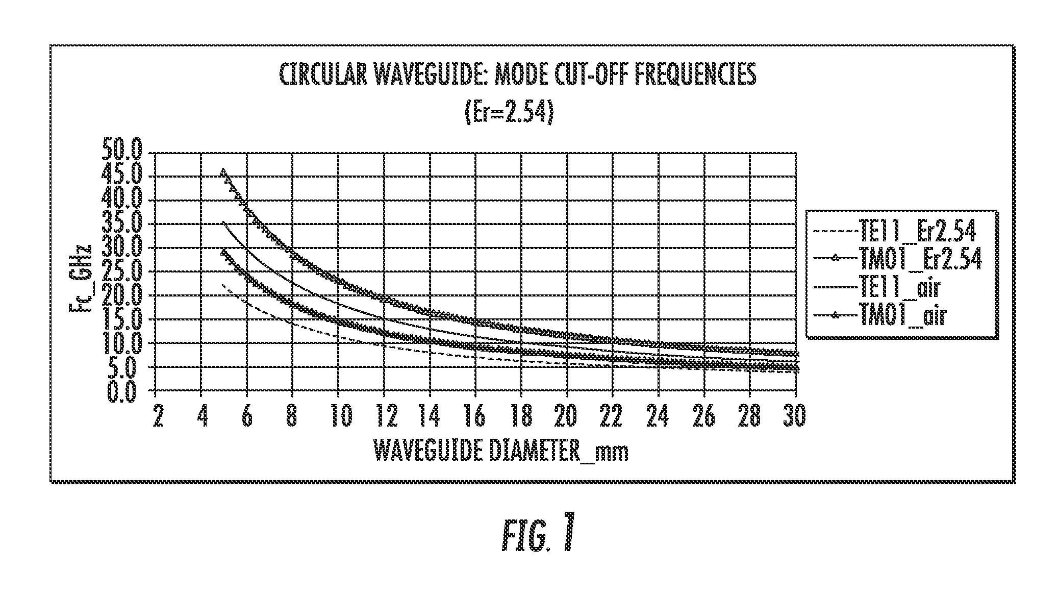
[0027]The cut off frequency of each mode in a dielectric filled circular waveguide is determined by the internal diameter of the waveguide and the dielectric properties of the material. The amplitude and phase of energy, propagating in the waveguide, in a specific mode depends upon the waveguide dimensions, any discontinuity present in the waveguide and the frequency of operation. Because it has the lowest cut-off frequency, the fundamental mode in a circular waveguide is TE11. The next cut-off frequency in a circular waveguide is for TM01. The cut-off frequencies for the TE11 and TM01 mode of propagation in an air filled and dielectric filled (Er=2.54) open ended ci...


PUM


Abstract

A feed assembly for a reflector antenna having a unitary portion of dielectric material, a proximal end of the unitary portion configured for connection with the reflector antenna. The unitary portion having a waveguide portion extending between the proximal end and a sub reflector support having a sub reflector surface at a distal end. The waveguide portion and the sub reflector surface covered with an RF reflective material. The unitary portion may be cost effectively formed via, for example injection molding and or machining. Alternatively, the feed assembly may be formed as a horn feed, without a sub reflector.

Description

BACKGROUND[0001]1. Field of the Invention[0002]This invention relates to feed assemblies for reflector antennas. More particularly, the invention provides improvements in reflector antenna feed assembly electrical performance and cost efficiency via a unitary solid dielectric self supporting feed assembly.[0003]2. Description of Related Art[0004]Many broadcast and or communications systems require antennas with a highly directional signal reception and or transmission characteristic. Reflector antennas focus a signal received by a dish shaped reflector upon the feed horn of a centrally mounted receiver. Because the dish shaped reflector only focuses a signal received from a single direction upon the receiver or a sub reflector that further directs the signal to the receiver, reflector antennas are highly directional. When the reflector antenna is used to transmit a signal, the signals travel in reverse, also with high directivity.[0005]Reflector antennas with a sub reflector support...

Claims


Application Information

Patent Timeline
Patent Type & Authority Patents(United States)
IPC IPC(8): H01Q19/19
CPCH01Q1/24H01Q19/193H01Q19/09H01Q1/526
Inventor SYED, JUNAIDHILLS, CHRIS
Owner COMMSCOPE TECH LLC
Why Eureka
Try Eureka