Thread cutting insert

a cutting edge and insert technology, applied in the direction of cutting inserts, shaping cutters, manufacturing tools, etc., can solve the problem of hardly achieving the effective use of the insert main body, and achieve the effect of increasing the number of thread cutting edges that can be used in one insert main body, reducing the cost of thread cutting, and reducing the number of cutting edges

Inactive Publication Date: 2011-03-22
MITSUBISHI MATERIALS CORP
View PDF44 Cites 34 Cited by
  • Summary
  • Abstract
  • Description
  • Claims
  • Application Information

AI Technical Summary

Benefits of technology

[0015]Therefore, in such a thread cutting insert, the thread cutting edges are formed on the side ridgelines of at least two of the projecting faces among the total of four of the projecting faces of the pair of the cutting edge sections formed on the common edge section of the front and back faces of the insert main body. As a result, even in the case where the insert main body is of a polygonal flat plate shape such as the above mentioned triangular flat plate shape and the front and back faces are polygonal faces having the above edge sections as corner sections, one corner section enables use of the thread cutting edge at least twice, and the number of the thread cutting edges that are available for use with a single insert main body can be increased. In particular, if the above pair of the cutting edge sections are formed such that the side ridgelines of the two projecting faces are symmetric about the center line of the edge section that passes between these projecting faces when seen from the direction facing the front and back faces, then it becomes possible to have the shape of the thread cutting edges with these projecting faces serving as rake faces or the shape of the thread cutting edges with the projecting faces on the front and back faces side serving as rake faces, made the same to be used.
[0034]As described above, according to the present invention, the number of thread cutting edges that can be used in one insert main body can be increased, and effective use of the insert main body can be achieved while enabling economical thread cutting processing.

Problems solved by technology

As a result, in this type of thread cutting insert in which the portion to be used as a cutting edge is already small enough, even if the insert main body is formed from a super hard alloy or the like, effective use of the insert main body is hardly achieved.

Method used


Image

  • Thread cutting insert
  • Thread cutting insert
  • Thread cutting insert

Examples


Embodiment Construction

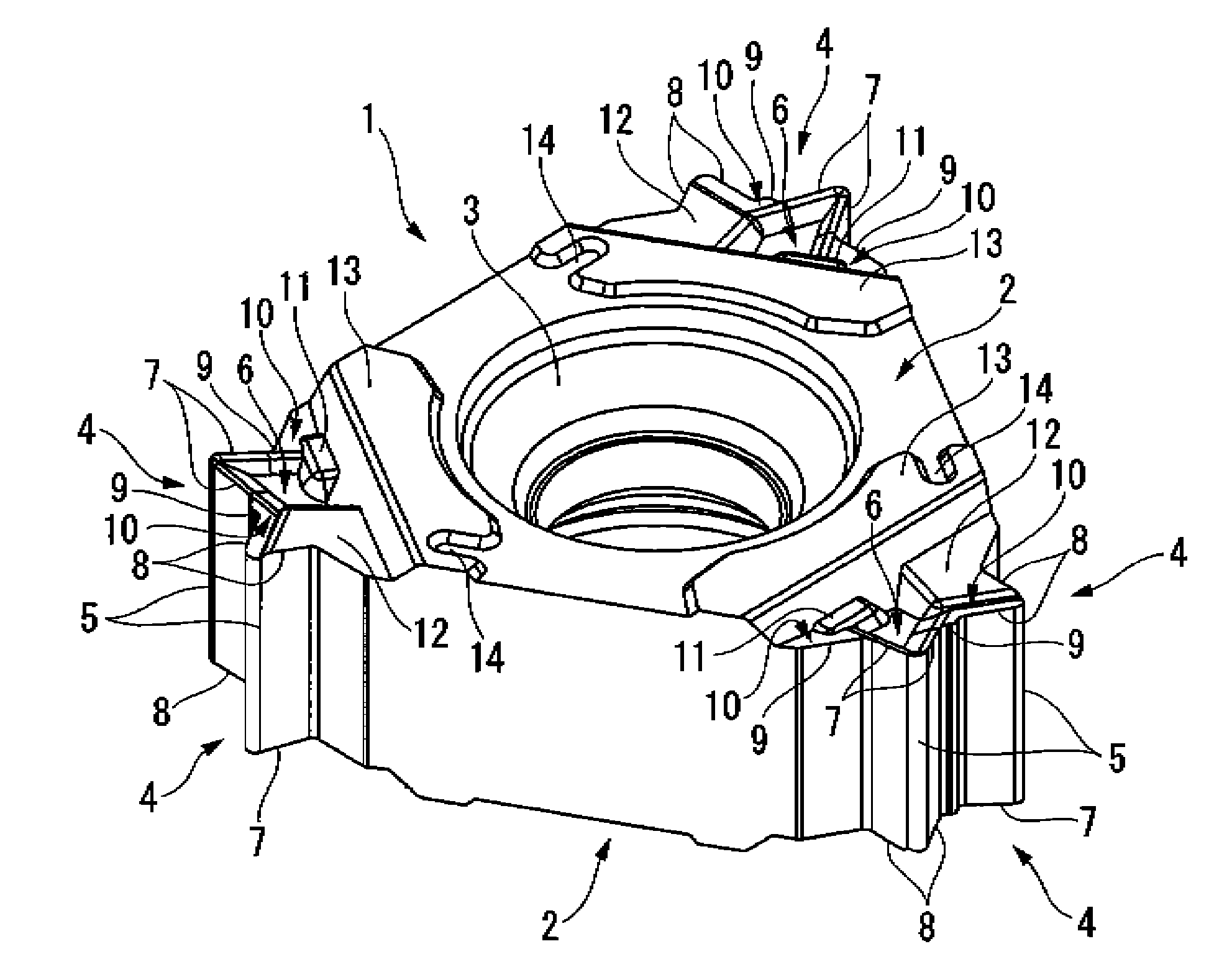
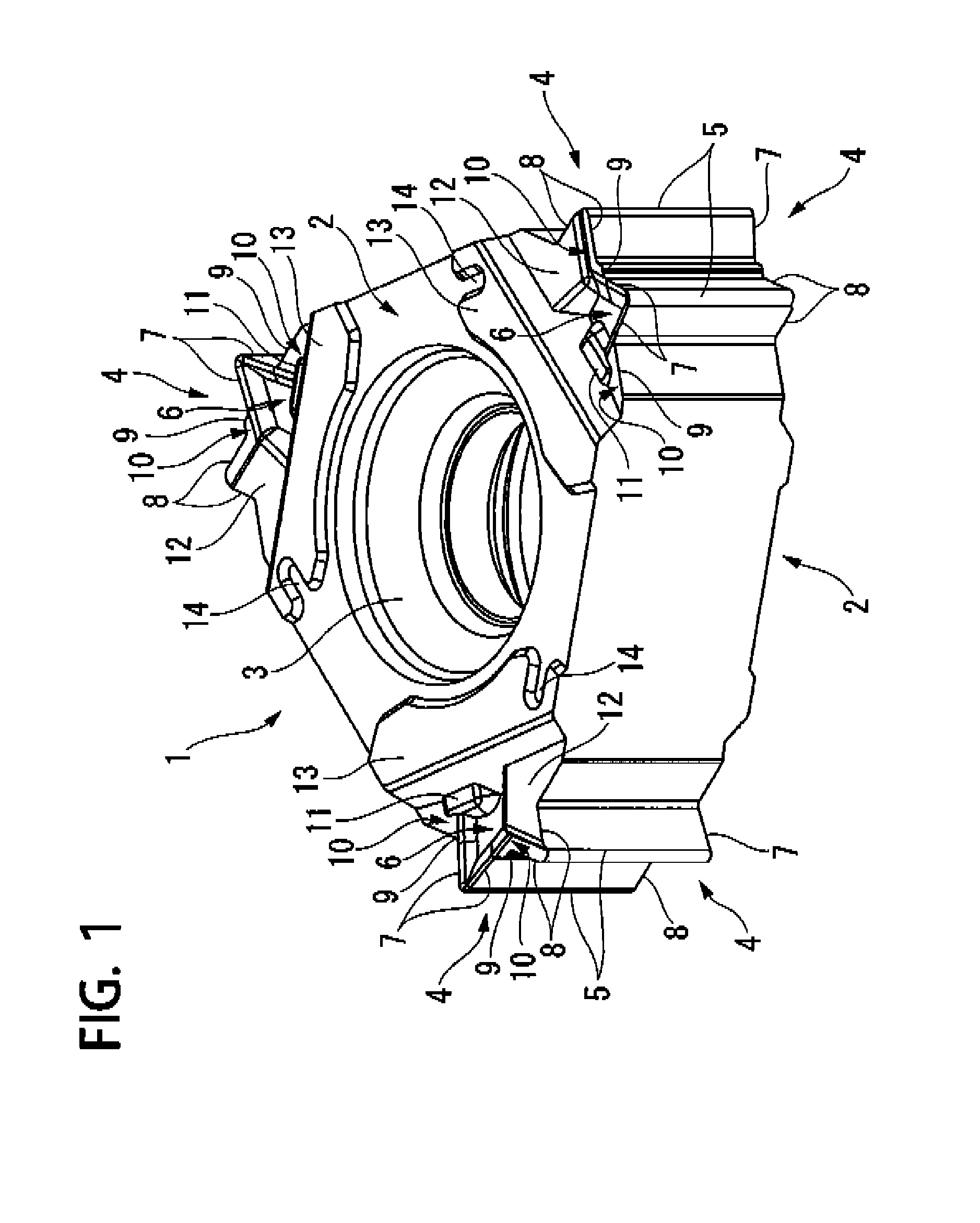
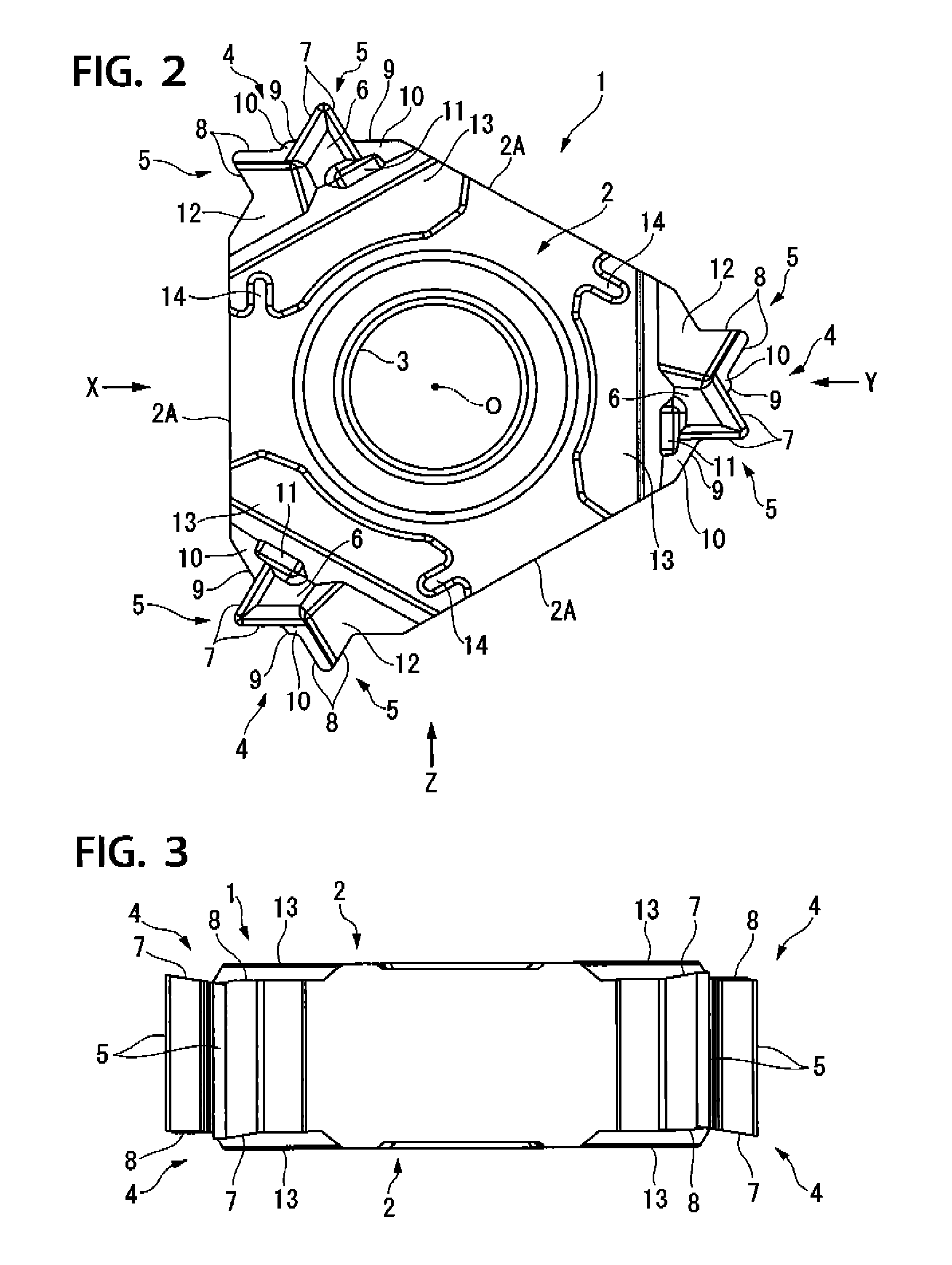
[0062]FIG. 1 through FIG. 9 show a first embodiment of the present invention for a case of forming a triangular thread in a workpiece. In the present embodiment, an insert main body 1 is formed from a hard material such as a super hard alloy, in a substantially equilateral triangular flat plate shape as shown in FIG. 2, and in the center of a pair of equilateral triangular faces 2 that form the front and back faces of the insert main body 1, there is opened a cross-sectionally round attachment hole 3 that passes through the insert main body 1 in the thickness direction thereof (vertical direction in FIG. 1, FIG. 3 to FIG. 5, FIG. 7 to FIG. 10). The insert main body 1 is 120° rotationally symmetric about an axis O that passes through the center of the attachment hole 3 as shown in FIG. 2.

[0063]Moreover, the insert main body 1, for each of three corner sections 4 which are common edge sections of the equilateral triangular face 2 where three side ridgelines intersect with each other, ...


PUM

PropertyMeasurementUnit
crossing angleaaaaaaaaaa

Abstract

In this thread cutting insert, on a common edge section of front and back faces of an insert main body, there is formed a pair of cutting edge sections that project from the edge section when seen from a direction facing the front and back faces, and on at least two of four projecting faces that respectively face the front and back face sides of the pair of these cutting edge sections, there is formed a thread cutting edge with the projecting face serving as a rake face.

Description

BACKGROUND OF THE INVENTION[0001]Priority is claimed on Japanese Patent Application No. 2007-61464, the contents of which are incorporated herein by reference.[0002]1. Field of the Invention[0003]The present invention relates to a thread cutting insert that is held on a tool main body of a detachable insert type cutting tool, for performing thread cutting on a workpiece.[0004]2. Description of Related Art[0005]As this type of thread cutting insert, in the following Patent Documents 1 to 4 for example, there have been proposed various kinds of thread cutting inserts in which, in each corner section of a triangular face of a triangular flat plate shaped insert main body, there is formed a cutting edge section that forms a convex V shape when seen from the direction facing the triangular face, and the convex V shape face of this cutting edge section serves as a rake face, on the side ridgelines of which there are formed a pair of thread cutting edges that form a convex V shape correspo...

Claims


Application Information

Patent Timeline
Patent Type & Authority Patents(United States)
IPC IPC(8): B23P15/36
CPCB23B27/065B23B27/141B23B2200/049B23B2200/081B23B2200/086B23B2200/087Y10T407/235B23B2200/323B23B2215/68Y10T407/1946Y10T407/24Y10T407/23B23B2200/321B23G5/00B23B27/14B23B27/22
Inventor NADA, YUTAKAICHINOSEKI, OSAMU
Owner MITSUBISHI MATERIALS CORP
Why Eureka
Try Eureka