Mask material conversion

a mask material and conversion technology, applied in the field of masking techniques, can solve the problems of unfavorable photolithographic techniques, poorly defined, and non-uniform features in the substrate,

Active Publication Date: 2011-03-22
MICRON TECH INC
View PDF173 Cites 417 Cited by
  • Summary
  • Abstract
  • Description
  • Claims
  • Application Information

AI Technical Summary

Problems solved by technology

Due to factors such as optics and light or radiation wavelength, however, photolithography techniques each have a minimum pitch below which a particular photolithographic technique cannot reliably form features.
This poor uniformity, in turn, can cause poorly defined and non-uniform features to be formed in the substrate.
As a result, the electrical performance of integrated circuits formed in the substrate may be degraded or the integrated circuits may be unusable.

Method used


Image

  • Mask material conversion
  • Mask material conversion
  • Mask material conversion

Examples


Embodiment Construction

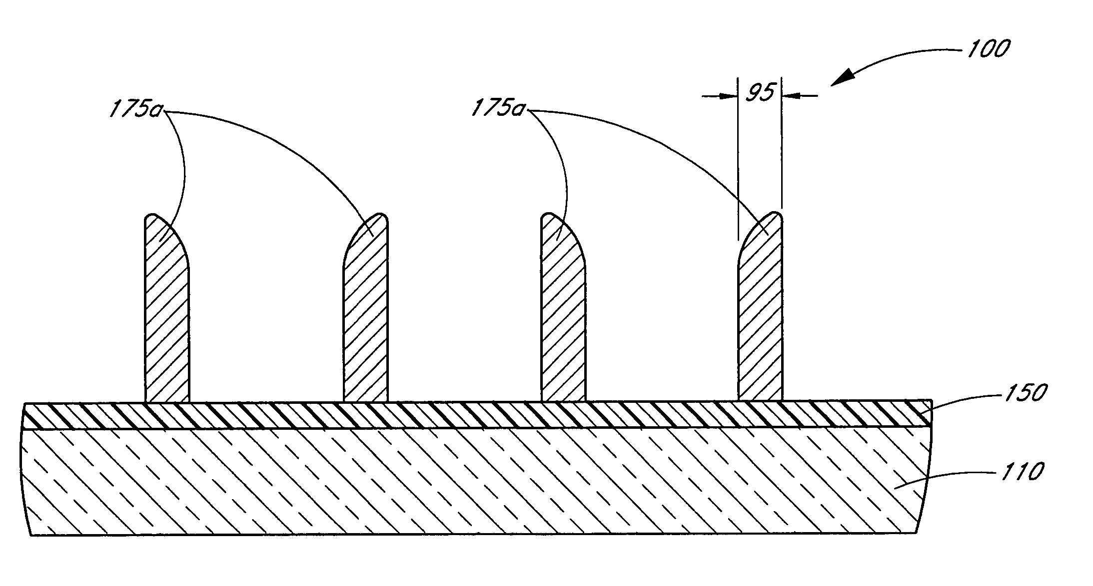
[0042]It has been found that the poor quality of some spacer patterns is due to difficulties depositing conformal layers of spacer material and / or etching this material to form spacers. Because spacers are typically formed out of the vertically extending parts of blanket layers of spacer material over a complex mask topography, the conformality of the layers will affect the uniformity, e.g., the widths, the heights and the physical placement, of the spacers formed from the layers. It will be appreciated that the more conformal a layer is, the more closely it replicates the shape of the surface on which it is deposited.

[0043]As critical dimensions continue to decrease, however, the aspect ratios of the spaces, or openings, between mandrels continue to increase. This is partly due to the desire to pack features more closely together by reducing the widths of the spaces between mandrels. In addition, in common methods of transferring patterns, both the spacers and an underlying layer a...


PUM

PropertyMeasurementUnit
wavelengthaaaaaaaaaa

Abstract

The dimensions of mask patterns, such as pitch-multiplied spacers, are controlled by controlled growth of features in the patterns after they are formed. To form a pattern of pitch-multiplied spacers, a pattern of mandrels is first formed overlying a semiconductor substrate. Spacers are then formed on sidewalls of the mandrels by depositing a blanket layer of material over the mandrels and preferentially removing spacer material from horizontal surfaces. The mandrels are then selectively removed, leaving behind a pattern of freestanding spacers. The spacers comprise a material, such as polysilicon and amorphous silicon, known to increase in size upon being oxidized. The spacers are oxidized to grow them to a desired width. After reaching the desired width, the spacers can be used as a mask to pattern underlying layers and the substrate. Advantageously, because the spacers are grown by oxidation, thinner blanket layers can be deposited over the mandrels, thereby allowing the deposition of more conformal blanket layers and widening the process window for spacer formation.

Description

REFERENCE TO RELATED APPLICATIONS[0001]This application is related to the following: U.S. patent application Ser. No. 10 / 931,772 to Abatchev et al., filed Aug. 31, 2004, entitled Critical Dimension Control, U.S. patent application Ser. No. 10 / 934,778 to Abatchev et al., entitled Method for Integrated Circuit Fabrication Using Pitch Multiplication, U.S. patent application Ser. No. 10 / 931,771 to Tran et al., filed Aug. 31, 2004, entitled Methods for Increasing Photo-Alignment Margins, and U.S. patent application Ser. No. 10 / 934,317 to Sandhu et al., entitled Methods to Align Mask Patterns.BACKGROUND OF THE INVENTION[0002]1. Field of the Invention[0003]This invention relates generally to integrated circuit fabrication and, more particularly, to masking techniques.[0004]2. Description of the Related Art[0005]As a consequence of many factors, including demand for increased portability, computing power, memory capacity and energy efficiency in modern electronics, integrated circuits are c...

Claims


Application Information

Patent Timeline
Patent Type & Authority Patents(United States)
IPC IPC(8): G03F1/00
CPCH01L21/0337H01L21/0338H01L21/308H01L21/32139H01L21/31144H01L21/311
Inventor ABATCHEV, MIRZAFER K.SANDHU, GURTEJ
Owner MICRON TECH INC
Why Eureka
Try Eureka