Vibration motor

a vibration motor and motor technology, applied in the direction of mechanical vibration separation, dynamo-electric machines, structural associations, etc., can solve the problems of shortening the life of the motor, wear and black powder, and taking time to reach the target amount of vibration, so as to achieve the effect of simple structure and increase the amount of vibration

Inactive Publication Date: 2011-03-22
MPLUS
View PDF8 Cites 50 Cited by
  • Summary
  • Abstract
  • Description
  • Claims
  • Application Information

AI Technical Summary

Benefits of technology

[0011]The present invention provides a linear vibrator with a simple structure that can increase the amount of vibration.

Problems solved by technology

However, the brush type structure using such commutator has a shorter motor life due to mechanical friction and electrical sparks, which cause wear and black powder, between the brush and the commutator when the motor rotates.
Moreover, when voltage is supplied to the motor, it takes time to reach the target amount of vibration by the rotational inertia of the motor.
Thus, it is difficult to implement the vibration appropriate for touchscreen phones.
However, in the linear vibrator, which is designed to vibrate in the perpendicular direction, the mass installed in the linear vibrator is required to secure a vertical displacement within 4 mm of space so as to generate vibrations, so that the space limitation becomes much significant and increasing the amount of vibration may be restricted.

Method used


Image

  • Vibration motor
  • Vibration motor
  • Vibration motor

Examples


Embodiment Construction

[0030]The features and advantages of this invention will become apparent through the below drawings and description.

[0031]A linear vibrator according to certain embodiments of the present invention will be described below in more detail with reference to the accompanying drawings. Those components that are the same or are in correspondence are rendered the same reference numeral regardless of the figure number, and redundant descriptions are omitted.

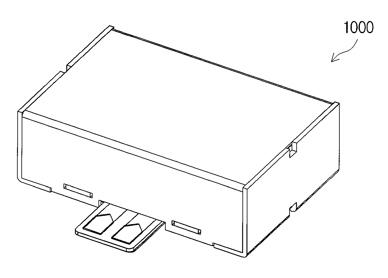
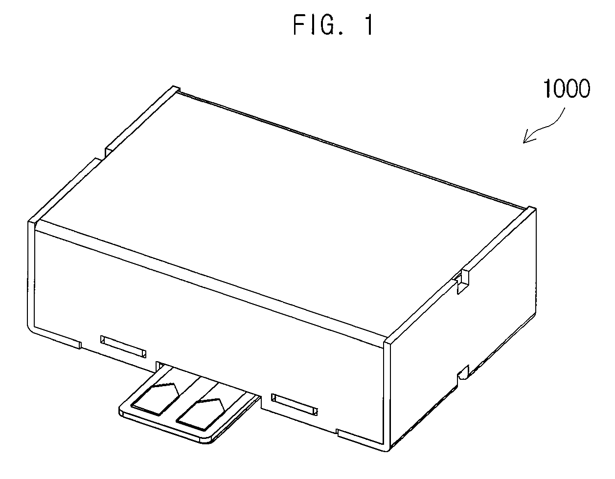
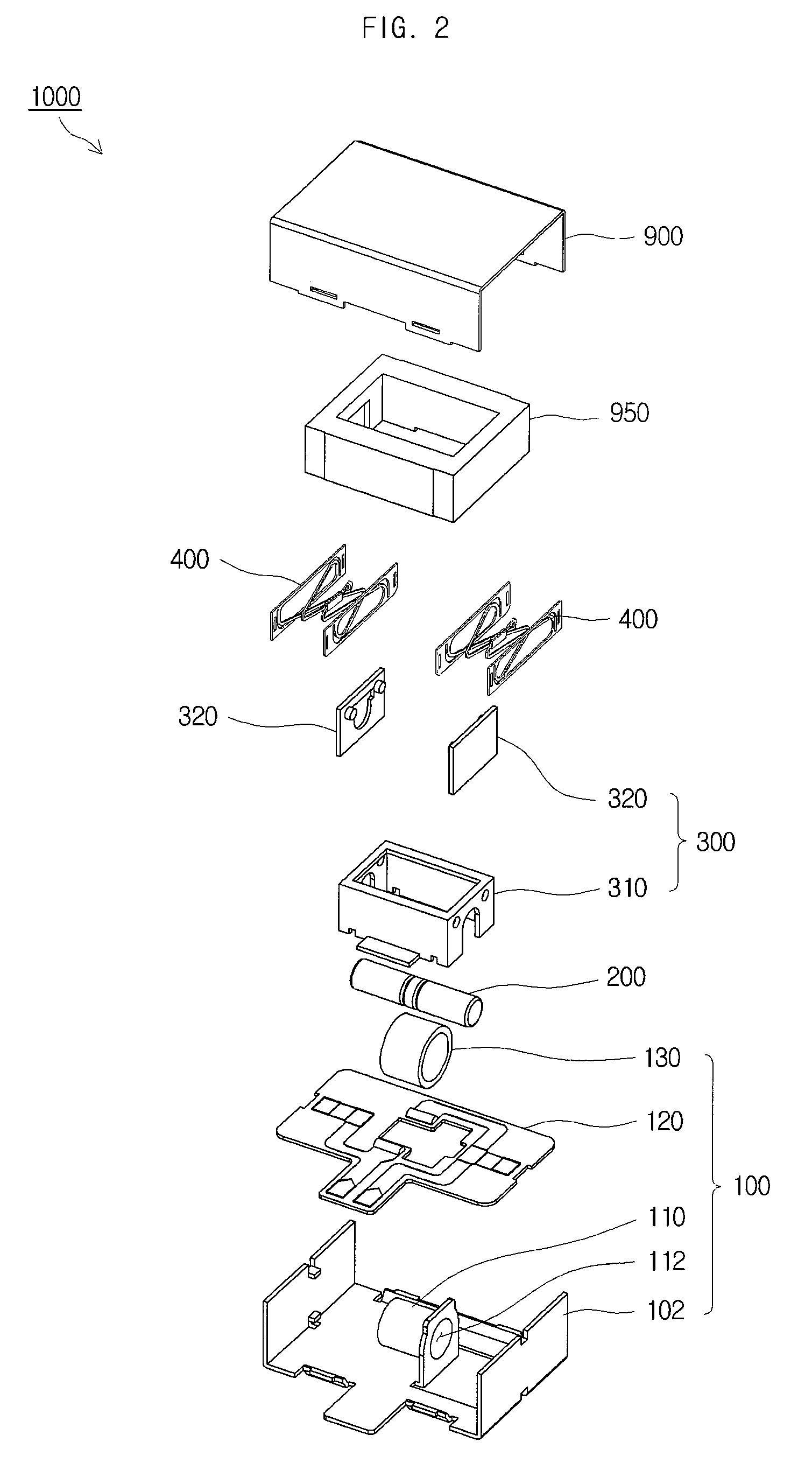
[0032]FIG. 1 is a perspective view of a linear vibrator 1000 in accordance with an embodiment of the present invention, and FIG. 2 is an exploded perspective view of a linear vibrator 1000 in accordance with an embodiment of the present invention. As illustrated in FIGS. 1 and 2, a linear vibrator 1000 according to an embodiment of the present invention includes a base 102, a coil unit 130, a magnet 200, a weight 950 and a leaf spring assembly 400. Thus, the linear vibrator 1000 can increase the range of vibration displacement in a struc...


PUM


Abstract

A linear vibrator is disclosed. The linear vibrator includes a base, a coil unit, which is coupled to the base, a magnet, which is coupled to the coil unit such that the magnet can move relatively, and a plurality of leaf springs, which are interposed between the magnet and the base. Here, the plurality of leaf springs face one another and are coupled to one another Thus, the linear vibrator can increase the range of vibration displacement in a structure and increase the amount of vibration in the linear vibrator. Also, even though the linear vibrator becomes thinner, the range of displacement can be increased because the weight is vibrated horizontally.

Description

CROSS-REFERENCE TO RELATED APPLICATIONS[0001]This application claims the benefit of Korean Patent Application No. 10-2009-0061749, filed with the Korean Intellectual Property Office on Jul. 7, 2009, the disclosure of which is incorporated herein by reference in its entirety.BACKGROUND[0002]1. Technical Field[0003]The present invention relates to a linear vibrator.[0004]2. Description of the Related Art[0005]A linear vibrator is a part that converts electrical energy into mechanical vibrations by using the principle of generating electromagnetic forces, and is commonly installed in a mobile phone to generate a soundless vibrating alert. With the rapid expansion of mobile phone markets and increased functionalities added to the mobile phone, mobile phone parts are increasingly required to be smaller and better. As a result, there has been an increased demand for the development of a new structure of linear vibrator that can improve the shortcoming of conventional linear vibrators and ...

Claims


Application Information

Patent Timeline
Patent Type & Authority Patents(United States)
IPC IPC(8): H02K7/06H02K35/00H02K33/00H02K11/00
CPCH02K33/16B06B1/045H02K33/06
Inventor LEE, KYOUNG-HOCHOI, JUN-KUNJUN, JAE-WOOOH, HWA-YOUNGLEE, KWANG-HYUNGBANG, JE-HYUNPARK, SEOK-JUNKIM, YONG-JINHAN, SEUNG-HEON
Owner MPLUS
Why Eureka
Try Eureka