Coating for cutting implements

a technology for cutting implements and coatings, applied in envelope openers, manufacturing tools, transportation and packaging, etc., can solve the problems of typical household and office knives and paper trimmers that cannot achieve a long-lasting cutting edge that can withstand long-term use, and achieve the effects of improving wear resistance, reducing user effort, and increasing hardness

Inactive Publication Date: 2011-03-29
ACME UNITED CORPORATION
View PDF181 Cites 10 Cited by
  • Summary
  • Abstract
  • Description
  • Claims
  • Application Information

AI Technical Summary

Benefits of technology

[0007]It is a further object of the present invention to provide a cutting implement having a coating that provides one or more of improved wear resistance, increased hardness, pleasing appearance, reduced user effort, and increased stain resistance.

Problems solved by technology

For example, typical household and office knives and paper trimmers have been unable to achieve a long-lasting cutting edge that withstands the wide variety of products being cut, at a competitive price.

Method used


Image

  • Coating for cutting implements
  • Coating for cutting implements
  • Coating for cutting implements

Examples


Embodiment Construction

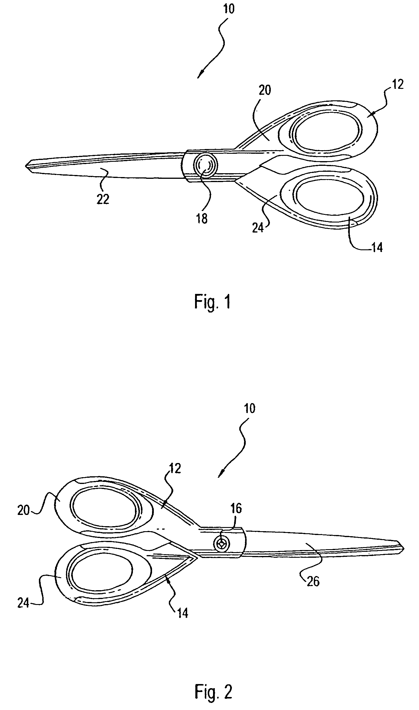
[0025]Referring now to the figures and in particular to FIGS. 1 and 2, a cutting implement in the form of a pair of scissors generally indicated by reference numeral 10 is illustrated.

[0026]Scissors 10 have a first half 12 pivotally connected to a second half 14. First and second halves 12, 14 are pivotally connected by conventional connection means, such as a screw 16 and a post 18. First half 12 can have a handle 20 and a blade 22. Similarly, second half 14 can have a handle 24 and a blade 26.

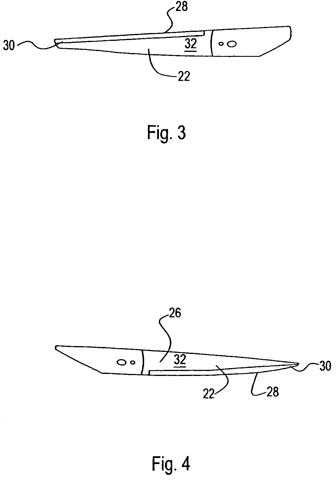
[0027]Each blade 22, 26 has a cutting edge 28. Preferably, cutting edge 28 is formed by way of a bevel 30 disposed on each blade 22, 26, respectively. Thus, scissors 10 provide a pair of complementary cutting blades 22, 26 for cutting stationery products, such as paper, cardboard, bristol board, and others.

[0028]Handles 20, 24 are preferably overmolded onto blades 22, 26, respectively. However, it should be recognized that each half 12, 14 of scissors 10 is described as having separate handle...


PUM

PropertyMeasurementUnit
thicknessaaaaaaaaaa
thicknessaaaaaaaaaa
surface roughnessaaaaaaaaaa

Abstract

A cutting implement having a cutting blade and a coating is provided. The coating has titanium chromium nitride and provides the blade with a satin silver appearance. In some embodiments, the titanium chromium nitride coating has a thickness in a range between about 0.3 microns and 0.5 microns, a surface roughness in a range of about 15 to 25×10−6 inch / inch, and a hardness in a range of about 5.7 to 9.1 gigapascals.

Description

CROSS-REFERENCE TO RELATED APPLICATIONS[0001]This is a continuation-in-part application that claims priority to U.S. application Ser. No. 10 / 720,578, filed Nov. 24, 2003, now U.S. Pat. No. 6,988,318, which is a continuation of PCT / US02 / 36314, filed Nov. 13, 2002, which claims priority to U.S. Provisional Application No. 60 / 338,575, filed Nov. 13, 2001, the entirety of which are incorporated by reference herein. This also is a continuation-in-part application that claims priority to U.S. Design application Ser. No. 29 / 213,571, filed Sep. 20, 2004, now U.S. Pat. No. D. 526,879 the entirety of which is incorporated by reference herein. This also is a continuation-in-part application that claims priority to U.S. application Ser. No. 10 / 695,429, filed Oct. 28, 2003, which claims priority to U.S. Provisional Application No. 60 / 421,581, filed Oct. 28, 2002, the entirety of which are incorporated by reference herein. This application is related to and incorporates by reference a co-pending ...

Claims


Application Information

Patent Timeline
Patent Type & Authority Patents(United States)
IPC IPC(8): B26B9/00
CPCB26B9/00B26B13/00B26D1/0006B43L23/008B43L23/08B43M7/002C23C14/0021C23C14/0036C23C14/0641C23C14/325C23C14/35C23C30/00B26B25/005B26D2001/002B26D2001/004Y10T428/31678
Inventor BUCHTMANN, LARRYPIA, GARY
Owner ACME UNITED CORPORATION
Why Eureka
Try Eureka