Water-cooled air conditioning system using condenser water regeneration for precise air reheat in dehumidifying mode

a technology of air conditioning system and condenser water, which is applied in the field of air conditioning system, can solve the problems of air conditioning system that cannot and the cooling system cannot operate long enough to remove the amount of moistur

Active Publication Date: 2011-03-29
CLIMATE MASTER
View PDF2 Cites 23 Cited by
  • Summary
  • Abstract
  • Description
  • Claims
  • Application Information

AI Technical Summary

Problems solved by technology

However, during periods of low space cooling demand, the cooling system will not operate long enough to remove the amount of moisture required to control indoor humidity.
Thus, there are situations where an air conditioning system must provide dehumidification independent of sensible cooling.

Method used


Image

  • Water-cooled air conditioning system using condenser water regeneration for precise air reheat in dehumidifying mode
  • Water-cooled air conditioning system using condenser water regeneration for precise air reheat in dehumidifying mode
  • Water-cooled air conditioning system using condenser water regeneration for precise air reheat in dehumidifying mode

Examples


second embodiment

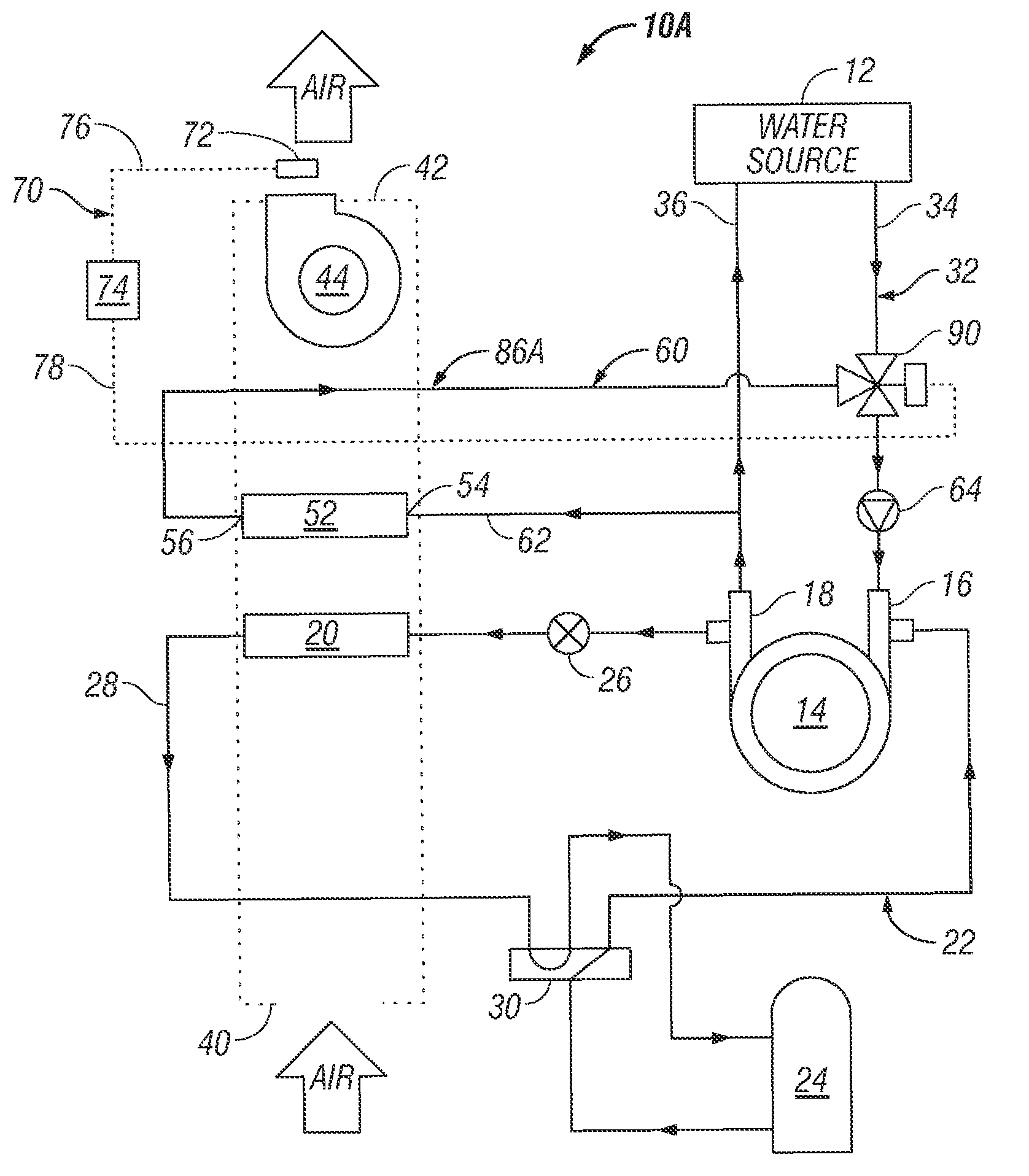
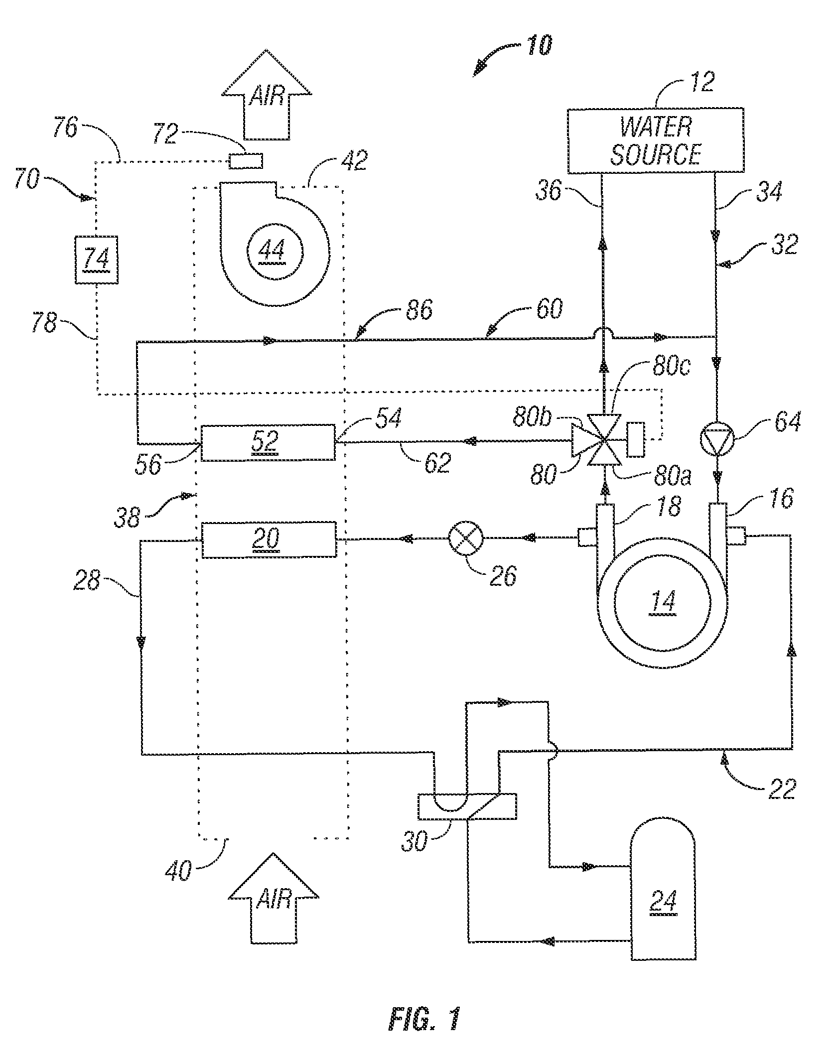
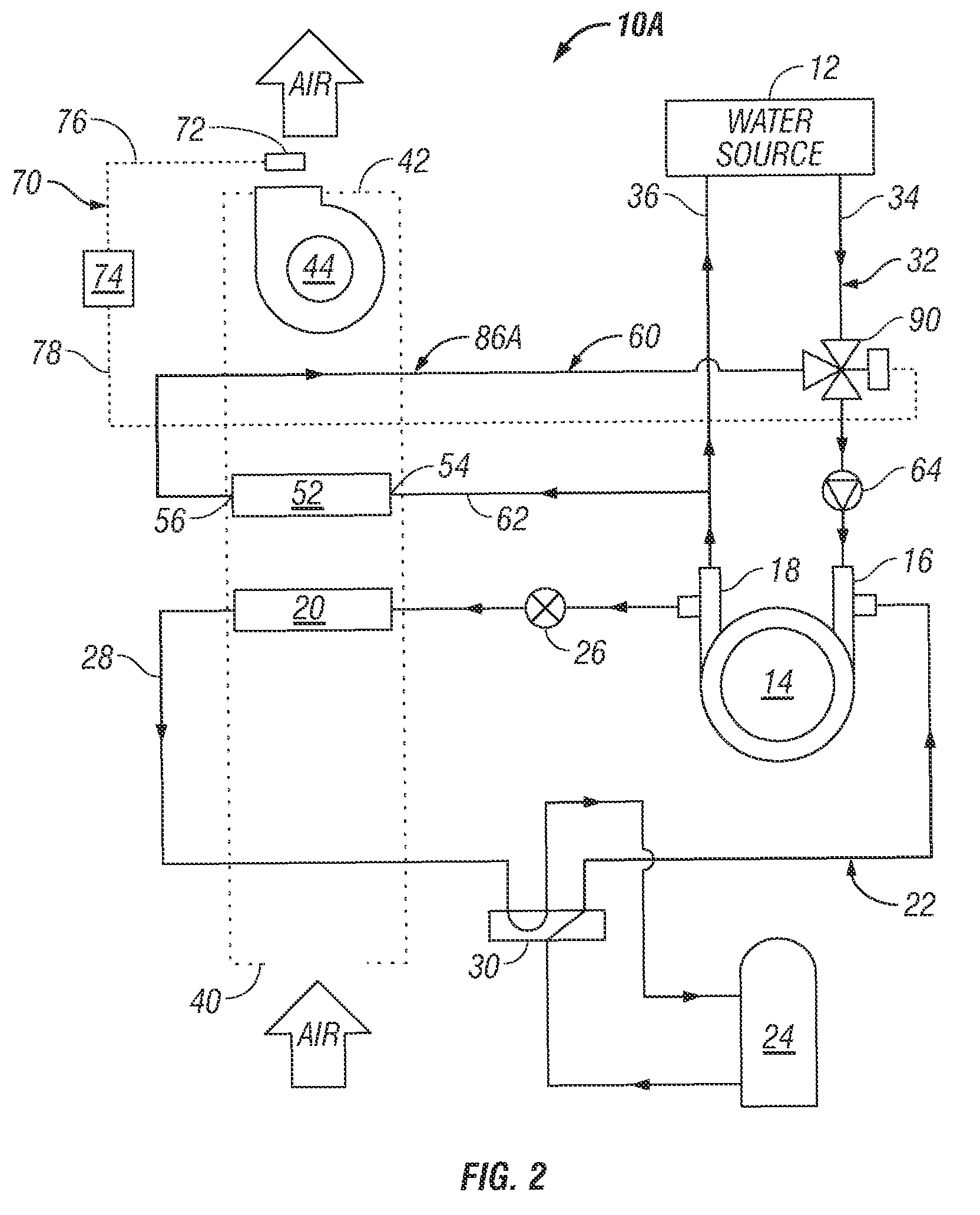
[0029]Turning now to FIG. 2, there is shown therein the present invention designated generally by the reference numeral 10A. The system 10A of FIG. 2 is similar to the system 10 of FIG. 1, and like reference numerals indicate like elements. More specifically, the system 10A comprises a condenser 14, an evaporator 20, a refrigeration circuit 22, and water condenser circuit 32. A similar air circuit 38 also is included.

first embodiment

[0030]The reheat assembly 86A differs from the reheat assembly 86 of FIG. 1 in that instead of the diverting valve 80 in the first embodiment, the control assembly 70 comprises a mixing valve 90. The mixing valve 90 is positioned in the supply conduit 34 of the condenser water circuit 32 at the junction of the reheat circuit 60 with the supply conduit. The control assembly 70 is similarly provided with a supply air temperature sensor 72 by which the controller 74 regulates the reheat circuit operation through the mixing valve 90. The mixing valve 90 serves the same function of proportioning or modulating the condenser water flow between the reheat circuit 50A and the water source 12. As in the reheat assembly 86 of FIG. 1, the pump 64 of the reheat assembly 86A of FIG. 2 can be repositioned to support condenser water flow in other modes, or to provide flow only for the reheat circuit 60, as may be desired.

third embodiment

[0031]the present invention is illustrated in FIG. 3, to which attention now is directed. The system 10B of FIG. 3 is similar to the systems 10 of FIG. 1 and 10A of FIG. 2, and like reference numerals indicate like elements. More specifically, the system 10B comprises a condenser 14, an evaporator 20, a refrigeration circuit 22, and water condenser circuit 32. A similar air circuit 38 also is included.

[0032]The reheat assembly 86B differs from the reheat assembly 86 of FIG. 1 and the reheat assembly 86A of FIG. 2 in that instead of the diverting valve 80 or the mixing valve 90, the control assembly 70 comprises a variable speed water pump control 92 connected to the pump 64. The pump 64 and pump control 92 are positioned in the reheat circuit 60 between the outlet 56 of the reheat heat exchanger 52 and the junction of the reheat circuit with the supply conduit 34 to the condenser 14. A check valve 94 is included in the reheat circuit 60 to prevent the water source supply water from ...


PUM


Abstract

A water-cooled air conditioning system using a regenerative condenser water circuit to reheat the supply air during a dehumidification mode. The air conditioning system may be any type of water-cooled system, including a water source heat pump or water-cooled air conditioner. The reheat circuit circulates water leaving the condenser through the reheat heat exchanger and then returns the water to the condenser inlet. Thus, the reheat circuit ensures that water leaving the condenser is warm enough to provide sufficient reheating for the supply air, regardless of the water source temperature. In addition, a modulation assembly controls the amount of water flowing through the reheat circuit, and thereby its temperature, so that the temperature of the reheated supply air can be maintained within a narrow range.

Description

[0001]This application claims the benefit of the filing date of provisional application Ser. No. 60 / 522,124, entitled “Condenser Water Regenerative Reheat for Water-Cooled Air Conditioners and Water-Source Heat Pumps,” filed Aug. 18, 2004, the contents of which are incorporated herein by reference. This application is a continuation application of application Ser. No. 11 / 161,808 entitled “Water-Cooled Air Conditioning System Using Condenser Water Regeneration for Precise Reheat in Dehumidifying Mode,” filed Aug. 17, 2005, the contents of which are incorporated herein by reference.FIELD OF THE INVENTION[0002]The present invention relates generally to air conditioning systems and, more particularly but without limitation, to water-cooled air conditioning and water source heat pump systems equipped with supply air reheat to provide dehumidification without sensible cooling.BACKGROUND OF THE INVENTION[0003]Modern heating and cooling systems are increasingly required to control indoor hu...

Claims


Application Information

Patent Timeline
Patent Type & Authority Patents(United States)
IPC IPC(8): F25B29/00F25D17/06F25D17/02
CPCF24F3/153F25B13/00Y02B30/52F25B2700/2103F25B2700/21173F25B2339/047
Inventor ELLIS, DANIEL L.NERURKAR, LAXMIKANT N.
Owner CLIMATE MASTER
Why Eureka
Try Eureka