
Apparatus for drop testing and method utilizing the same

a technology of apparatus and drop test, which is applied in the field of apparatus for drop test and a method, can solve the problems of high test cost and long preparation time, inconsistent results of each drop test, and high cos

Inactive Publication Date: 2011-03-29
POWERTECH TECHNOLOGY
View PDF3 Cites 5 Cited by
  • Summary
  • Abstract
  • Description
  • Claims
  • Application Information

AI Technical Summary

Benefits of technology

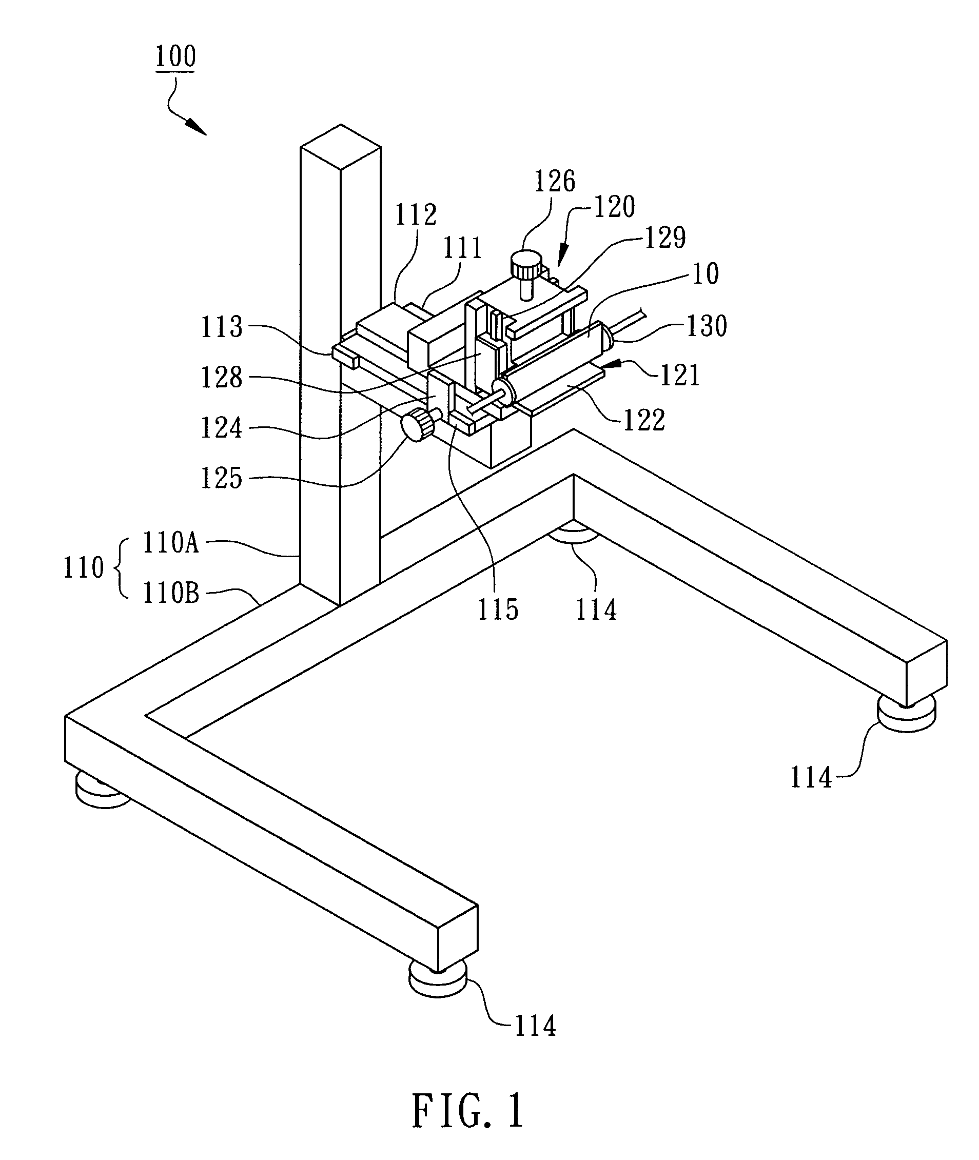
The present invention provides an apparatus for drop testing that can accommodate different sized test objects, drop angles, and testing conditions. The apparatus includes a support frame, a drop angle setting jig, and a fixture. The support frame has a sliding base with a horizontal sliding rail and a first stopping block. The jig is connected to the sliding base and has a second stopping block. The fixture holds the test object and has a first clamping face and a second clamping face with a smaller clamping clearance. The apparatus allows for quick and secure control of the test object's height, angle, and position, and ensures accurate measurement data. The technical effects of the invention include suitability for different sized test objects and drop surfaces, maintaining the same height, angle, and position during testing, and quick and secure return back to the reference position.

Problems solved by technology

Some problems are present in the prior art drop test:
1. Low repeatability of the test: The prior art test requires manual positioning of the height and angle of the test object, which may lead to inconsistent drop angles and dropped surfaces and result in inconsistent results for each drop test.
2. High test costs and long preparation times: Since the test has low repeatability, numerous testers are required, and each different design requires new additional testers.
Particularly during the product development period, each test has a high price, and drop testing is a destructive experiment so that repeating tests leads to high costs.
When there are different package type test objects or application environments, the prior art apparatus for drop testing does not support different drop test conditions.
Since each manufacturer may have different drop test standards, each test condition requires a different apparatus for drop testing, which can lead to very high costs.

Method used


Image

  • Apparatus for drop testing and method utilizing the same
  • Apparatus for drop testing and method utilizing the same
  • Apparatus for drop testing and method utilizing the same

Examples


Embodiment Construction

[0044]With reference to the attached drawings, the present invention is described by means of the embodiments below.

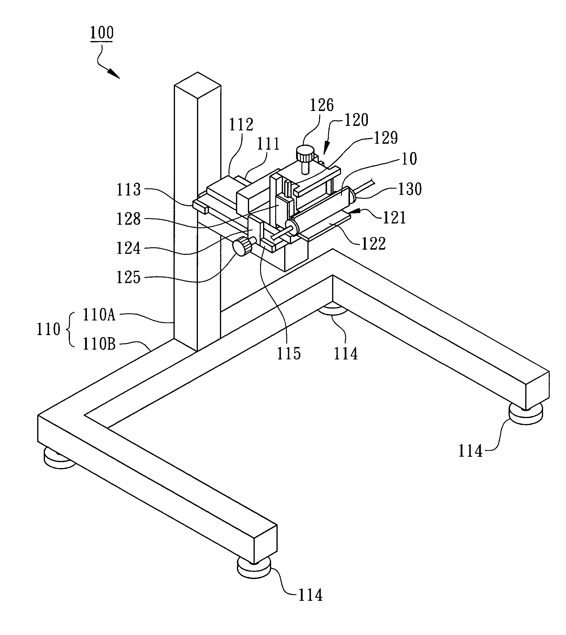
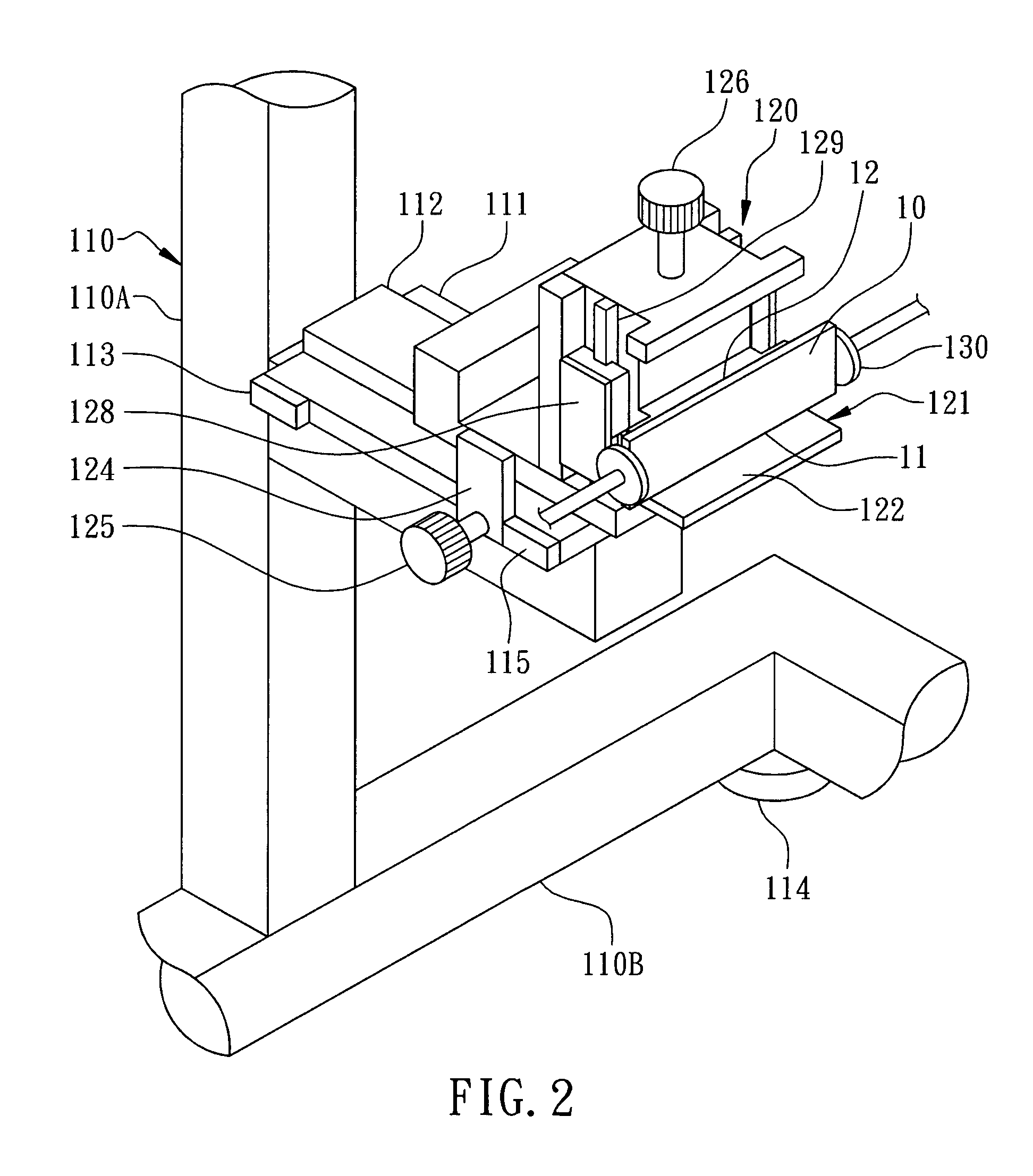
[0045]According to a first embodiment of the present invention, an apparatus for drop testing is shown in FIG. 1. The apparatus 100 for drop testing comprises a support frame 110, a drop angle setting jig 120 and a fixture 130, and the apparatus 100 for drop testing is used for performing a drop test on a test object 10 to evaluate its shock resistance. The test object 10 can be a long strip-shaped memory module, such as a DIMM (Dual In-Line Memory Modules) or a SO-DIMM (Small Outline Dual In-Line Memory Modules). The test object 10 can also be other electronic devices, or flip chip packaged structures, lead-frame packaged structures, multi-chip packaged structures or other typical packaging structures. Since there are various chip packaging types, each manufacturer may have its own testing standards, and the adjustable apparatus for drop testing of the present inventi...


PUM

PropertyMeasurementUnit
heightsaaaaaaaaaa
heightsaaaaaaaaaa
heightsaaaaaaaaaa

Abstract

An apparatus for drop testing is disclosed. The apparatus has a drop angle setting jig that horizontally moves on a support frame and positions a test object at a predetermined angle by clamping with a fixture. The jig provides a second datum plane and is connected to a moveable holding frame, with the holding frame providing a first datum plane. After the fixture clamps the testing object, the jig can be pulled back without touching the testing object, and the testing object stays still. Therefore, the testing object can be precisely positioned. Furthermore, with the sliding track and the stopping block, the jig is able to quickly return back to the reference position.

Description

BACKGROUND OF THE INVENTION[0001]1. Field of the Invention[0002]The present invention relates to the static or dynamic balance of a machine or device, and, more particularly, to an apparatus for drop testing and a method to utilize the same.[0003]2. Description of the Related Art[0004]In order to ensure products maintains their original quality in operational environments and during transportation, such as after the packaging process for packaged chip structure, some final quality tests such as aging tests, electrical tests, tensile tests, solder ball connection strength tests, etc., are performed to ensure quality and reliability. Subsequently, the packaged chip products are assembled into memory modules which can be utilized in standard electronic products, such as computers, mobile phones, digital cameras, PDAs, etc. Therefore, the requirements for impact and stress tolerances are higher and the related tests are more important. The packaging industry has established a strict tes...

Claims


Application Information

Patent Timeline
Patent Type & Authority Patents(United States)
IPC IPC(8): G01N3/00
CPCG01N3/303
Inventor SU, TING-FENG
Owner POWERTECH TECHNOLOGY
Learn More