Chemical analysis device

a chemical analysis and device technology, applied in the direction of analysis using chemical indicators, laboratory glassware, instruments, etc., can solve the problems of difficult to avoid contamination of the portion by residual samples or reagents, and mutual contamination of the channel or liquid storage unit, so as to prevent deterioration of analysis accuracy and test accuracy, and avoid contamination

Inactive Publication Date: 2009-01-15
HITACHI HIGH-TECH CORP
View PDF2 Cites 13 Cited by
  • Summary
  • Abstract
  • Description
  • Claims
  • Application Information

AI Technical Summary

Benefits of technology

[0015]A chemical analysis device for performing a chemical analysis or genetic test that can suppress deterioration of analysis accuracy and test accuracy while avoiding contamination by residual samples or reagents remaining in the device and having no complicated configuration can be constructed.

Problems solved by technology

In a system in which different liquid samples or reagents are pipetted to perform an analysis or a test, a channel or a liquid storage unit used for pipetting is frequently used in common for different samples or reagents, which causes a problem that the channel or liquid storage unit mutually becomes a source of contamination due to residual samples or reagents.
However, among portions used repeatedly, there has a portion that comes into contact with liquids and there is a problem that it is difficult to avoid contamination of the portion by residual samples or reagents.
However, according to a technology described in Japanese Patent Application Laid-Open Publication No. 2000-121650, there is a problem that a means for washing a portion including a reagent cell is needed, complicating the configuration of an analysis device.
A technology described in Japanese Unexamined Patent Application Publication (Translation of PCT Application) No. 9-504690 also needs a means for sealing a cell in which an amplification reaction occurs and thus, there is also a problem that the configuration of an analysis device becomes complicated.
In addition, stirring of a solution needed in the course of a reaction and also pipetting and dropping could also lead to contamination when analyzed repeatedly.

Method used


Image

  • Chemical analysis device
  • Chemical analysis device
  • Chemical analysis device

Examples


first embodiment

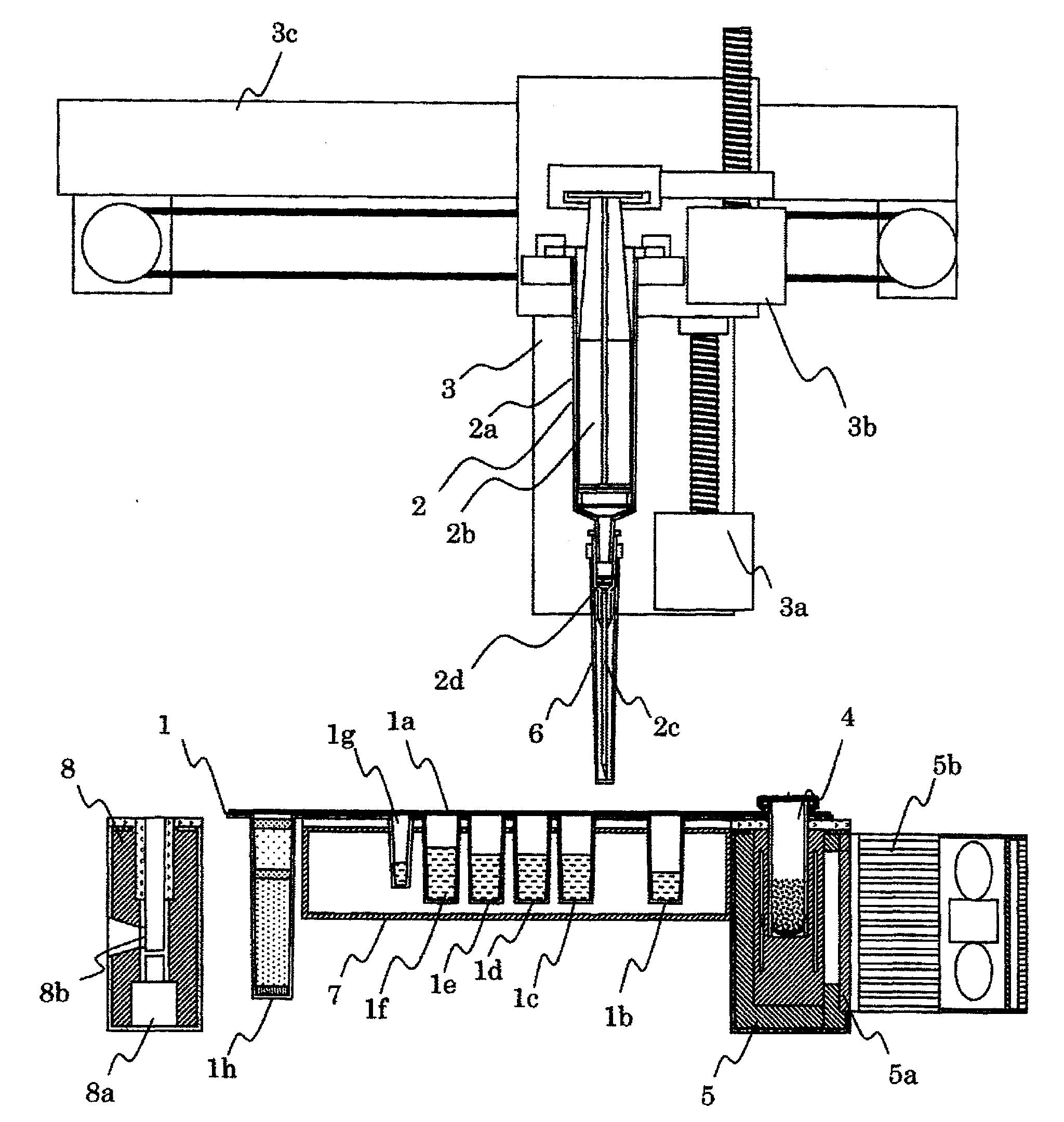
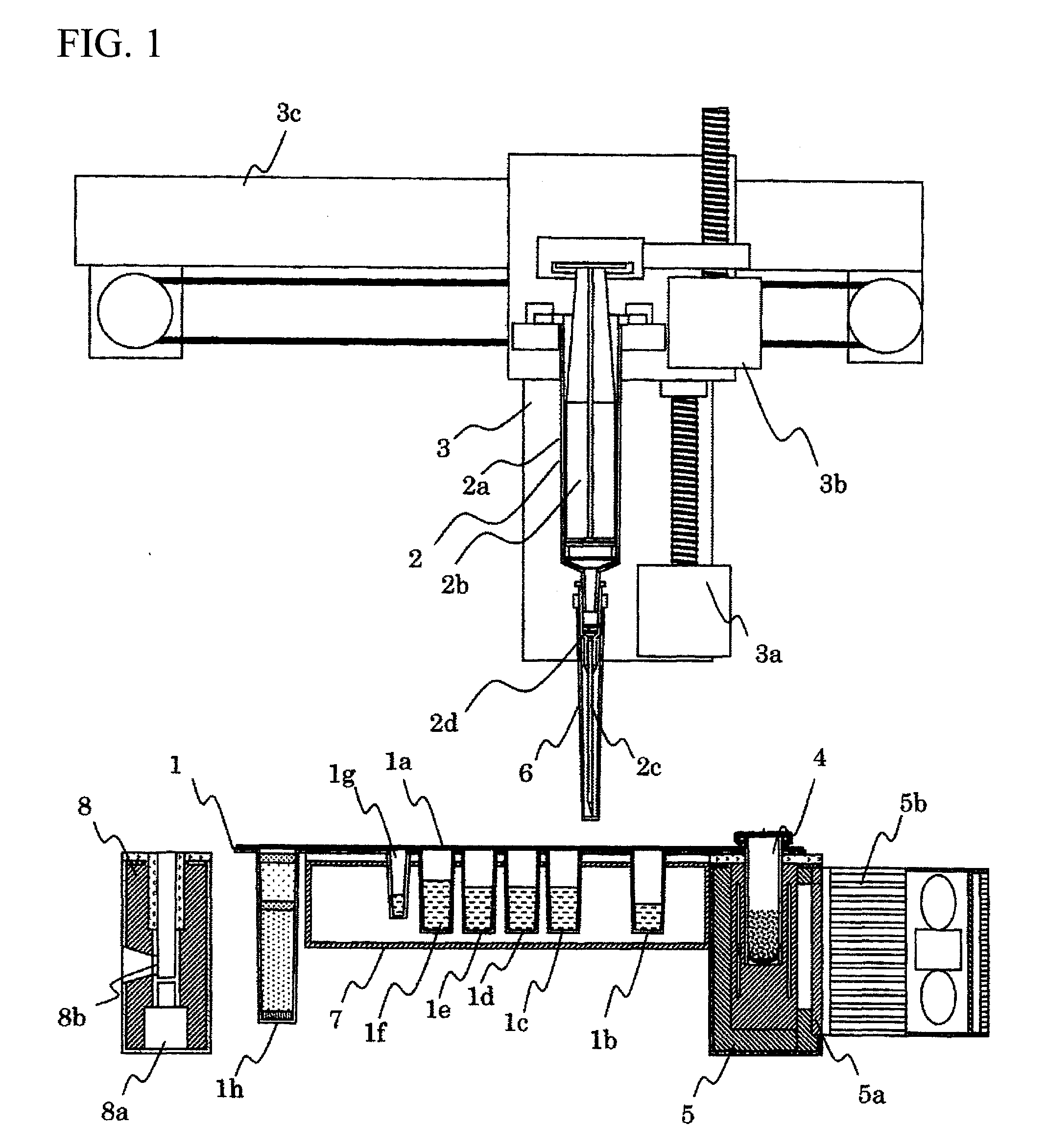
[0068]FIG. 1 to FIG. 4 are diagrams for illustrating the configuration of a genetic testing device in the present invention and FIG. 5 is a flow chart of a testing process in a tubercle bacillus test. FIG. 6 to FIG. 8 are diagrams illustrating a device state in each testing process.

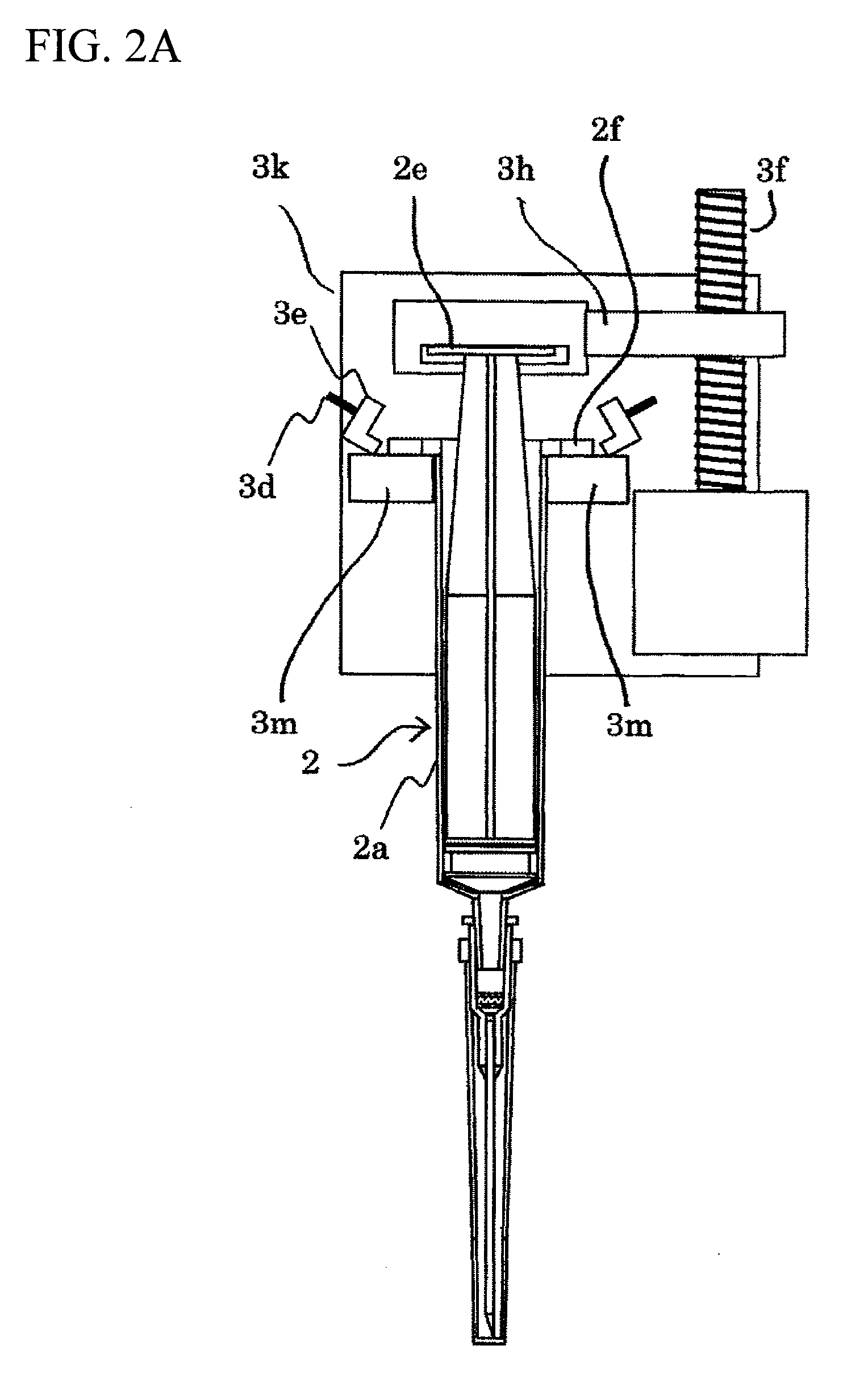
[0069]In FIG. 1, a reagent cell 1 is filled with each reagent to be used for analysis and the reagent cell 1 is covered with a protective film 1a obtained by surface-coating a base material of PET (Polyethylene Terephthalate) with aluminum to prevent evaporation. A pipetting unit 2 is provided with a syringe 2a made of resin, a plunger 2b, and a needle unit 2c. The needle unit 2c contains a carrier 2d for capturing nucleic acid at a base thereof, and one pipetting unit 2 performs a triple role of piercing of the protective film 1a by the needle unit 2c, reagent pipetting, and nucleic acid purification.

[0070]Amounts of suction and dispensing of a solution such as a reagent and a sample by the pipetting uni...

second embodiment

[0092]In the second embodiment, as is clear from FIG. 9, a sample cell rotating unit 9 for mixing a sample solution and a nucleic acid binding reagent is provided. The sample cell is connected to a transmission unit 9a when fitted to the genetic testing device. A drive motor 9b rotates the transmission unit 9a via a belt mechanism 9c, thereby rotating the sample cell itself.

[0093]FIGS. 10A and 10B are diagrams showing a side cross section (FIG. 10 A) of the sample cell and an axial transverse section (in FIG. 10B) thereof. Like the axial transverse section shown in FIG. 10 B, convex portions are provided on an inner wall of the cell, thereby allowing stirring of a solution when the sample cell rotates.

[0094]According to the second embodiment of the present invention, in addition to being able to achieve an effect similar to that of the first embodiment, the treatment time can be reduced compared with mixing and stirring by suction and dispensing using the pipetting unit 2, by mixing...

third embodiment

[0098]In the third embodiment, the pipetting unit 2 uses two types of tips, a nucleic acid purification tip 10 and a solution pipetting tip 11, by attaching and detaching these tips. The pipetting unit 2 is initially configured by the syringe 2a and the plunger 2b, and the nucleic acid purification tip 10 and the solution pipetting tip 11 are each fitted to the reagent cell 1.

[0099]The nucleic acid purification tip 10 contains a carrier for capturing nucleic acid and the reagent cell 1 is covered with a protective film like in the first embodiment and further, a septum 12 is fitted inside the cell. The septum 12 is made from a material such as chloroprene rubber that has resistance to reagents encapsulated in a cell and is rich in elasticity. The protective film is manually removed from the reagent cell 1 by an operator immediately before the reagent cell being fitted to the genetic testing device or immediately thereafter and before an automatic operation being started.

[0100]The pi...


PUM


Abstract

A chemical analysis device capable of suppressing deterioration of analysis and test accuracy while avoiding contamination by residual samples or reagents and having no complicated configuration is constructed.A pipetting unit is equipped with a syringe, plunger, and needle unit in which a carrier for capturing nucleic acid and a detection cell is mounted on the needle unit. A pipetting unit drive system is configured so that the pipetting unit is detachable. After the detection cell is removed from the pipetting unit and fixed to a nucleic acid amplification detection unit, a suction / dispensing operation of samples / reagents is performed by the pipetting unit and components to be measured are captured by the carrier. Captured components are measured after being dispensed into the detection cell fixed to the nucleic acid amplification detection unit. Then, the detection cell is taken out from the nucleic acid amplification detection unit while mounted on the pipetting unit and the whole pipetting unit is removed from the pipetting unit drive system.

Description

BACKGROUND OF THE INVENTION[0001]1. Field of the Invention[0002]The present invention relates to a chemical analysis device equipped with a pipetting function of a liquid sample or a reagent to analyze chemical substances in the sample solution.[0003]2. Description of the Related Art[0004]In a system in which different liquid samples or reagents are pipetted to perform an analysis or a test, a channel or a liquid storage unit used for pipetting is frequently used in common for different samples or reagents, which causes a problem that the channel or liquid storage unit mutually becomes a source of contamination due to residual samples or reagents.[0005]Thus, replacement of a tip part of a pipetting means is assumed in the conventional technology. However, among portions used repeatedly, there has a portion that comes into contact with liquids and there is a problem that it is difficult to avoid contamination of the portion by residual samples or reagents.[0006]To prevent contaminati...

Claims


Application Information

Patent Timeline
IPC IPC(8): G01N35/10B01L3/02
CPCB01L3/502G01N35/10G01N2035/1062G01N2035/1051G01N2035/103
Inventor SEINO, TAISAKUUMETSU, HIROSHISAITO, MICHIHIROKANDA, TAKAYUKIHATTORI, KUMIKO
Owner HITACHI HIGH-TECH CORP
Why Eureka
Try Eureka