Connector device

a technology of connecting devices and connectors, which is applied in the direction of coupling device connections, electrical apparatus casings/cabinets/drawers, instruments, etc., can solve the problems of inoperableness, contact leg deformation to an undesired extent, and the smart card would not fit inside the card reader, so as to facilitate the introduction of the same, facilitate the ejection of the smart card, and eliminate the risk of jamming the smart card in the card reader

Inactive Publication Date: 2011-03-29
SONY ERICSSON MOBILE COMM AB
View PDF8 Cites 10 Cited by
  • Summary
  • Abstract
  • Description
  • Claims
  • Application Information

AI Technical Summary

Benefits of technology

[0025]Thus, the card connector according to the invention can serve as a smart built-in-device having two functions, i.e. being able to facilitate the ejection of the smart card from the card reader and / or to facilitate the introduction of the same into 10 the card reader when moved in and out of the card reader in any direction. It is an advantage with the invention that the risk of jamming the smart card in the card reader is eliminated. Moreover, another advantage is that the connecting device, i.e. the contact legs for electrical connection are more durable as there is no risk of the ends of the contact legs getting stuck or hooking onto parts of the smart card, e.g. the ends or edges of the smart card or the ends of cavities or holes in the smart card independently of which direction the smart card is moved when withdrawn from or introduced into the card reader. Thus, also the total cost for manufacturing and handling the device using such a card connector may be reduced. Furthermore, the risk for breaking or deforming the contact legs of the card reader due to jamming between its ends and the smart card is eliminated. This also means that the card connector according to the invention enables a more reliable connection between the connecting device and the smart card and a longer life time for the card connector. Furthermore, the invention may be applied in several various products, devices and versions making a more flexible usage and broader application of the invention.

Problems solved by technology

Consequently, there are currently many different smart cards for the usage together with portable electronic devices, and cards often at least one uneveness, e.g. a dent with edges that may hook into edges of a card, and some cards even have holes, e.g. through holes, for different reasons.
This may give rise to problems for a user, since the unevenness or hole may hook or get caught at the free end of the contact leg, whereby the contact leg is deformed and even destroyed so that it becomes inoperable.
One way of trying to solve this problem is to elongate the length of the free end such that there is a lesser risk of hooking thereon, but this is not possible in low profile card readers as the available space, i.e. height is limited, and such an extended free end would hit the bottom of the card reader before the contact leg is fully deflected, whereby the smart card would not fit inside the card reader or the contact leg would be deformed to an undesired extent.
The length of the protruding free end for known contact legs also involves an increased cost for the manufacturer of the portable electronic device as a certain additional volume of the device in general is dedicated for accommodating the height of the bent contact leg making the device larger than necessary.
Furthermore, the user has to push the card with his finger and / or use a separate, loose tool, pin or pen to be able to “hit” the edge of the card when pushing the card to eject for withdrawal or to introduce it, which means that if the smart card is hooked onto the free end of the contact leg the card might get jammed inside the card reader or the card reader be made inoperable as the contact leg is deformed or destroyed requiring maintenance of the card reader or the user is forced to buy a new card reader.
Moreover, this jamming of the smart card may urge the user to use too much force when trying to introduce or withdraw the card, whereby the card and / or the card reader may be damaged or the separate tool for pushing the card may not be useful or may even be destroyed.
Yet further, when a portable electronic device is to be equipped with a card reader, the handling and size of the portable electronic device are compromised as known contact legs, due their shape, require a certain height inside the card reader that is not suitable for low profile card readers.

Method used


Image

  • Connector device
  • Connector device
  • Connector device

Examples


Embodiment Construction

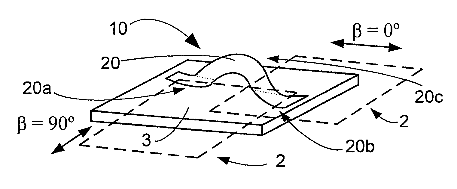
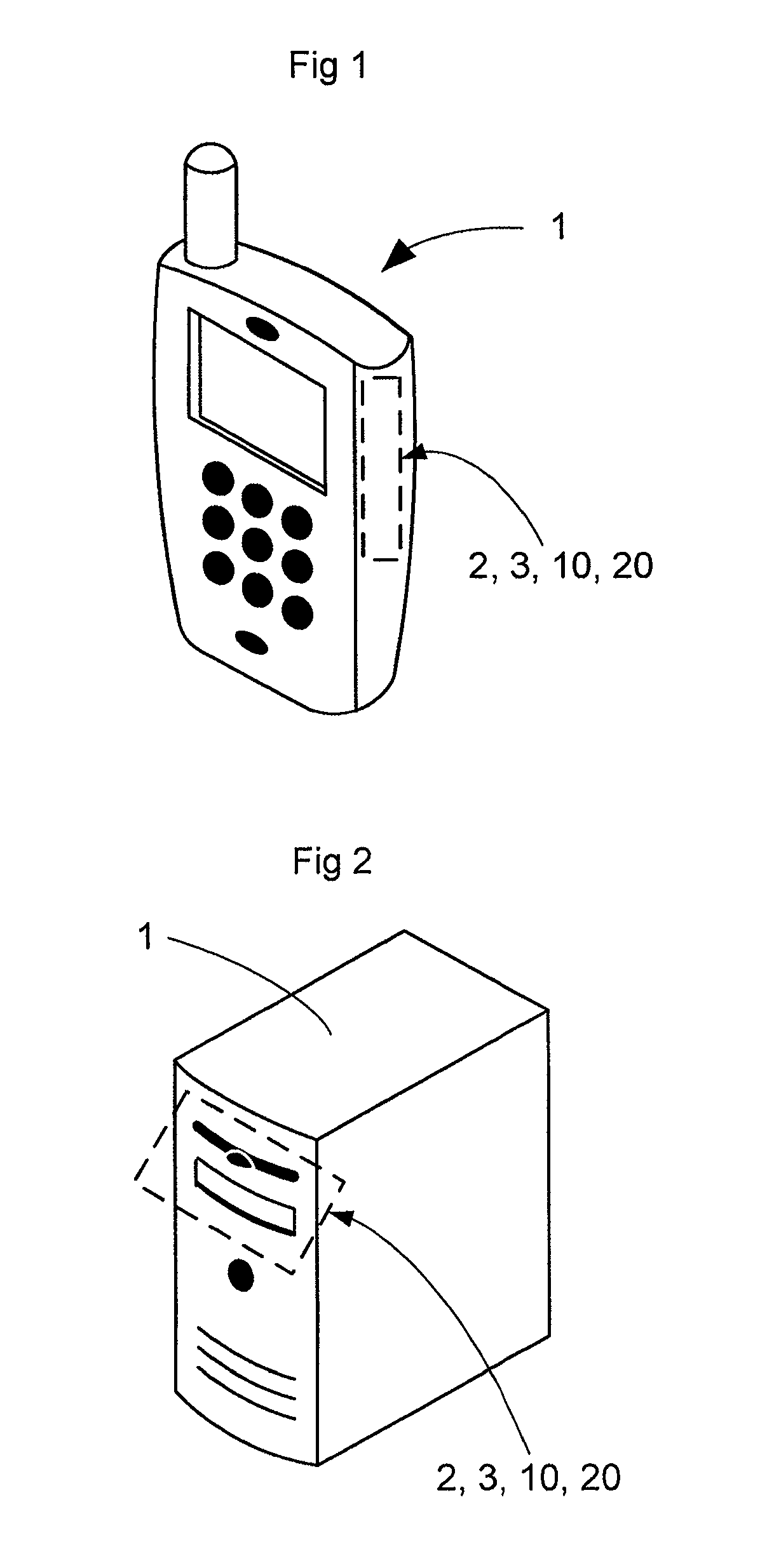
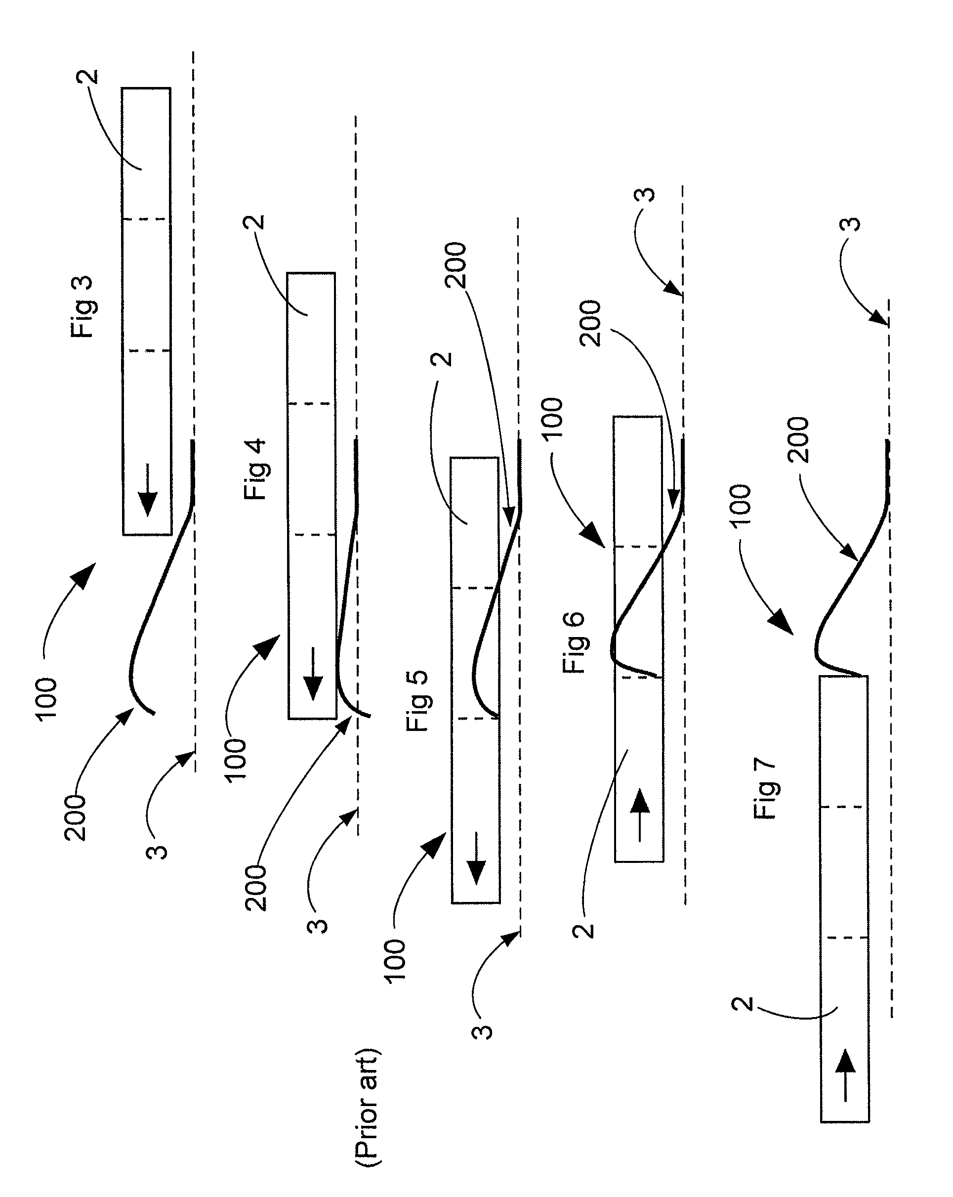
[0039]An aspect of the present invention will be described more fully hereinafter with reference to the accompanying drawings. FIGS. 1-2 and 8 to 14 show different views of the card connector 10 according to the invention while FIGS. 3 to 7 show different views of known card connectors when introducing into and withdrawing smart cards therefrom. This invention as shown in FIGS. 1-2 and 8 to 14 may, however, be realized in many different forms, shapes and structures and should not be construed as limited to the aspects set forth herein. Rather, these aspects are discussed so that this disclosure will be thorough and complete, and will fully convey the scope of the invention to those skilled in the art. Like numbers refer to like elements throughout.

[0040]The card connector 10 according to the disclosed invention is preferably, but not necessarily, intended for the usage together with a portable electronic device 1 (see FIG. 1) adapted to use a memory card or a smart card 2, which may...


PUM


Abstract

A card connector for ejection and introduction of smart cards is disclosed for usage in a portable electronic device comprising a card reader with a resilient card connecting device for operative connection of the smart card to the card reader by introducing the smart card into the card reader or disconnection of the smart card from the card reader by withdrawing the smart card from the card reader by moving the smart card in a plane being substantially in parallel with the plane of the card reader, wherein the card connecting device is extending substantially along a plane being inclined in relation to the plane of the card reader at an angle α, wherein the angle α is not 90°.

Description

TECHNICAL FIELD OF THE INVENTION[0001]The present invention relates to a connector device for facilitating connection of smart cards in card readers, i.e. to improve the reliability when introducing and withdrawing the smart card into and from the card reader. The card connector may advantageously be used in a portable electronic device having such a card reader.DESCRIPTION OF RELATED ART[0002]Today, there exist various ways of facilitating the connection of external cards, e.g. smarts cards, such as SIM and memory cards used in portable electronic devices, and smart cards for cable or satellite set up boxes. Moreover, there exist differently shaped and sized smart cards for different portable electronic devices, such as mobile telephones, smart phones, lap tops, communicators, cameras, digital audio players (e.g. MP3-players or iPods®), electronic photo frames, cable and satellite set up boxes etc. These smart cards may be different types of SIM cards with or without holes or reces...

Claims


Application Information

Patent Timeline
Patent Type & Authority Patents(United States)
IPC IPC(8): G06K7/00H05K5/00H01R39/00
CPCG06K7/0021H01R13/2442G06K7/01G06K17/00H01R13/24
Inventor NILSSON, ANDREAS
Owner SONY ERICSSON MOBILE COMM AB
Why Eureka
Try Eureka