Balance filter and duplexer

a balanced filter and duplexer technology, applied in the direction of waveguide devices, electrical equipment, electric signals output from packages, etc., can solve the problems of difficulty in securing a satisfactory wide pass band, the power durability of the first prior art is not good, and the electric signals output from the package may deviate from the opposite-phase relationship, etc., to achieve easy balance adjustment, improve bandpass characteristics, and improve power durability

Active Publication Date: 2011-03-29
TAIYO YUDEN KK
View PDF35 Cites 1 Cited by
  • Summary
  • Abstract
  • Description
  • Claims
  • Application Information

AI Technical Summary

Benefits of technology

[0011]The present invention has been made in view of the above-mentioned circumstances and provides a balance filter having improved power durability, easy balance adjustment after packaging and improved bandpass characteristics.

Problems solved by technology

However, the balance filter of the first prior art does not have good power durability because all of input power is applied to the single input SAW filter 34.
However, this method may affect the pass band and may have difficulty in securing a satisfactory wide pass band.
However, in practice, when the chip is incorporated into a package, the electric signals output from the package may deviate from the opposite-phase relationship.
However, this adjustment has difficulty because the input SAW filter outputs the signals that are in opposite phase.

Method used


Image

  • Balance filter and duplexer
  • Balance filter and duplexer
  • Balance filter and duplexer

Examples


first embodiment

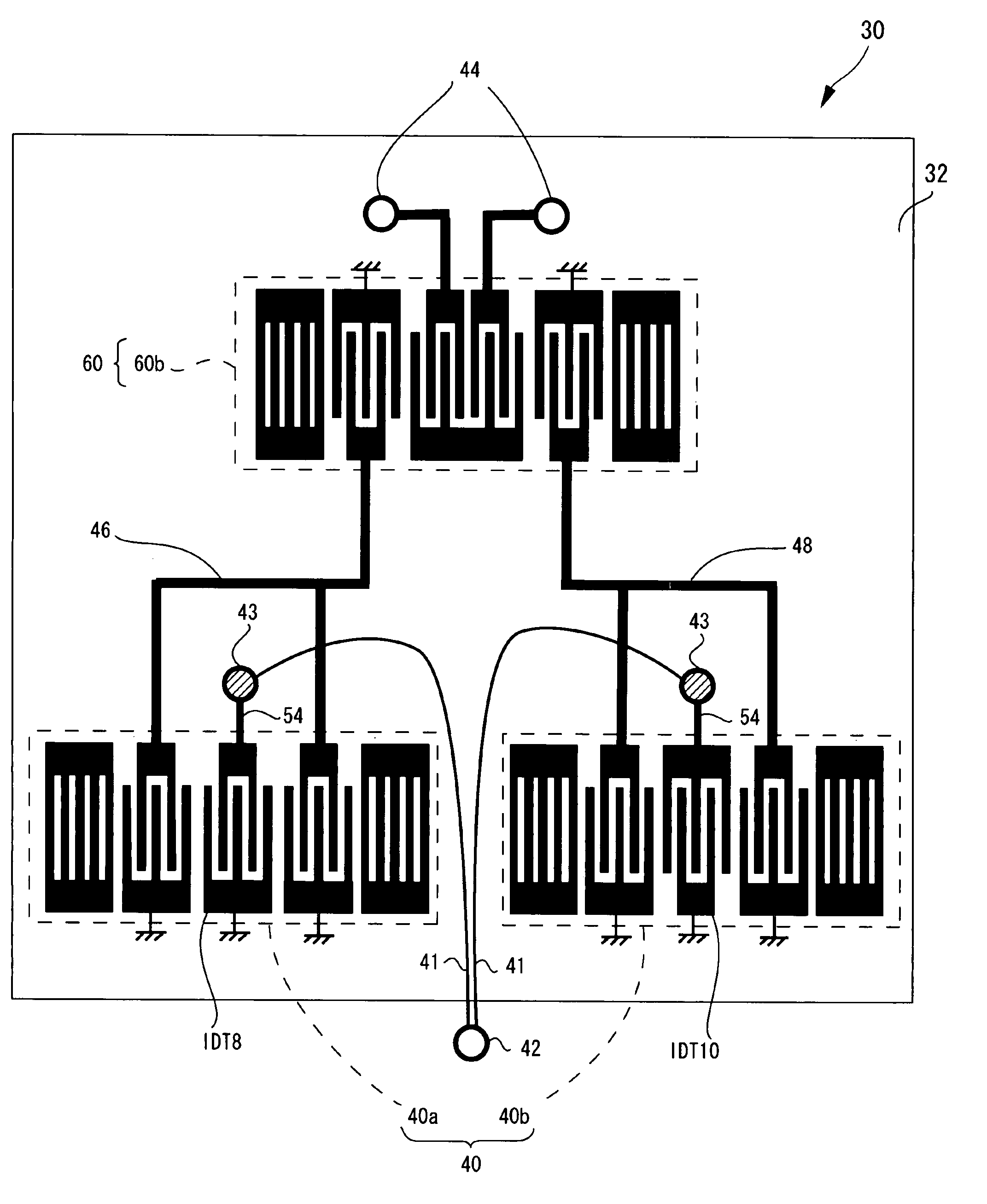
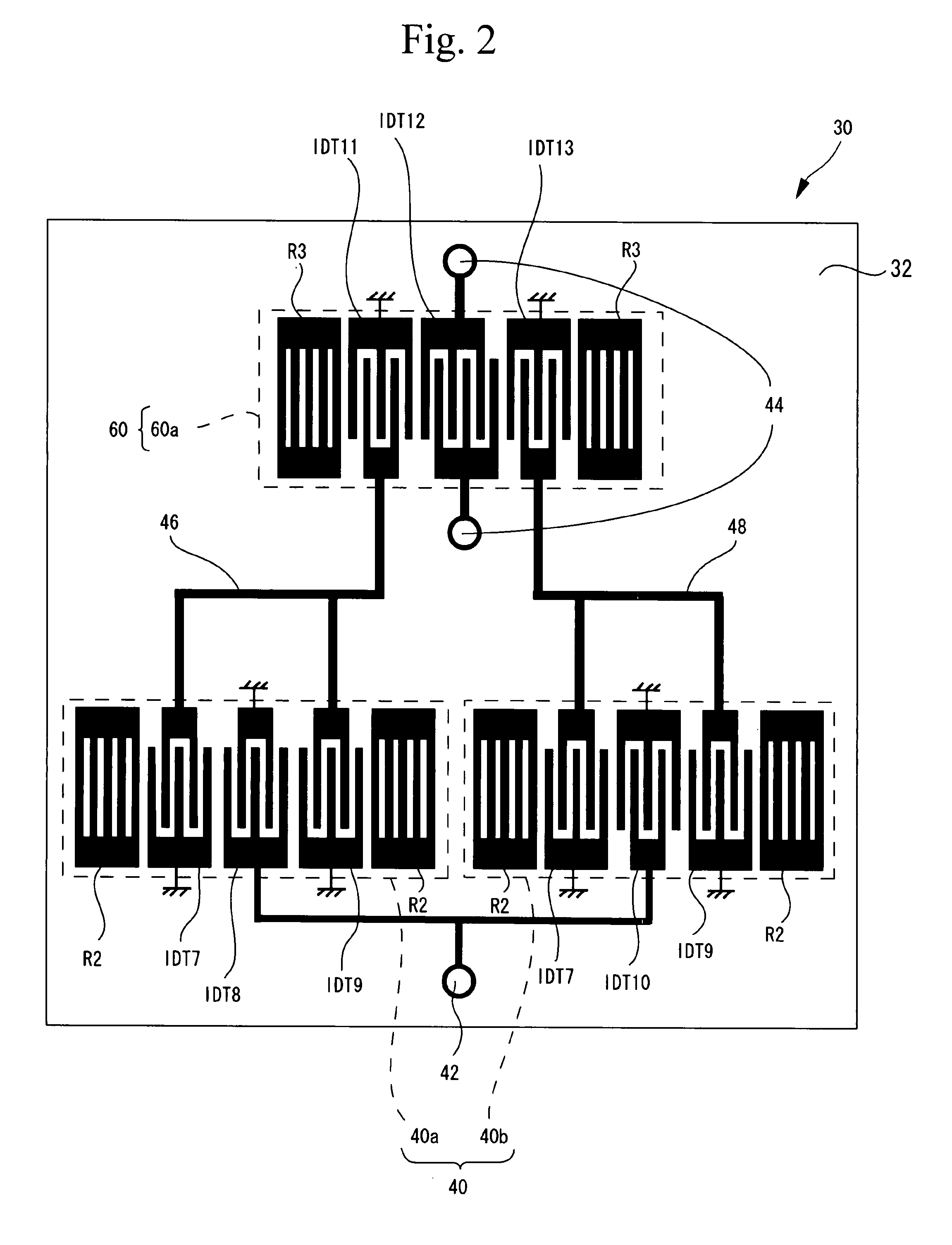
[0028]FIG. 2 schematically shows a balance filter in accordance with a first embodiment. Referring to FIG. 2, a balance filter 30 has a piezoelectric substrate 32 made of, for example, LiNbO3 or LiTaO3 on which IDTs and reflection electrodes are formed. The IDTs and the reflection electrodes may be formed by a metal film made of, for example, aluminum (Al). The balance filter 30 includes a first filter 40 that is a first multimode SAW filter, and a second multimode filter 60 that is a second multimode SAW filter. The first filter 40 is made up of filters 40a and 40b connected in parallel. The filter 40a has an input IDT8, an output IDT7, an output IDT9 and two reflection electrodes R2. The output IDT7 and the output IDT9 are located at both sides of the input IDT8 in a SAW propagation direction. The reflection electrodes R2 are located further out than the output IDT7 and the output IDT9 in the SAW propagation direction. Similarly, the filter 40b has an input IDT10, an output IDT7, ...

second embodiment

[0034]FIG. 3 schematically shows a balance filter in accordance with a second embodiment. Referring to FIG. 3, the balance filter 30 shown in FIG. 3 includes the first filter 40 and the second filter 60, which filters are formed on the piezoelectric substrate 32. The first filter 40 and the connection between the first filter 40 and the first terminal 42 of the second embodiment are the same as those of the first embodiment, and a description thereof will be omitted here. The second filter 60 includes a filter 60b, which is composed of the pair of reflection electrodes R3, the input IDT11, the input IDT13, and an output IDT14. One of a pair of electrodes of the output IDT14 is divided into two in the SAW propagation direction. Two second terminals 44 are respectively connected to the two divided electrodes. The two second terminals 44 run in a direction perpendicular to the SAW propagation direction. The first filter 40 and the second filter 60 are connected in the same manner as th...

third embodiment

[0039]FIG. 4 schematically shows a balance filter in accordance with a third embodiment. Referring to FIG. 4, the balance filter 30 has the first filter 40 and the second filter 60, which filters are formed on the piezoelectric substrate 32. The third embodiment has the same configurations as the first embodiment in terms of the first filter 40, and the connection between the first filter 40 and the first terminal 42, and a description thereof will be omitted here. The second filter 60 has two filters 60c. Each of the filters 60c has an identical configuration and is composed of the pair of reflection electrodes R3, the input IDT11, the input IDT13 and an output IDT15. One of two electrodes of the output IDT15 is connected to the second terminal 44, and the other is grounded. The filter 40a and one of the two filters 60c are connected in series by connection lines 50a and 50b. The connection line 50a connects the output IDT7 and the input IDT11, and the connection line 50b connects ...


PUM


Abstract

A balance filter includes a first filter having first multimode surface acoustic wave (SAW) filters connected in parallel, a second filter that is connected to the first filter and includes a second multimode SAW filter, a first terminal connected to the first filter, and second terminals connected to the second filter. An input terminal of the balance filter is one of the first and second terminals, and an output terminal thereof is the other. Electric signals transmitted from the first to second filters or vice versa are in opposite phase. Electric signals are input or output via the second terminals in opposite phase.

Description

BACKGROUND OF THE INVENTION[0001]1. Field of the Invention[0002]The present invention relates to balance filters and duplexers, and more particularly, to a balance filter having surface acoustic wave filters connected in parallel and a duplexer using such a balance filter.[0003]2. Description of the Related Art[0004]Recently, cellular phones have employed a receive system in which a received signal is of differential type (balance type) in order to restrain common mode noise in an RF circuit. Thus, the RF circuit needs RF devices of differential type (balance type).[0005]Japanese Patent No. 3391347 discloses a balance filter (hereinafter referred to as first conventional art). FIG. 1 schematically shows the first conventional art. Referring to FIG. 1, a balance filter 30 includes an input surface acoustic wave filter 34 and an output surface acoustic wave filter 36, each of which filters is formed on a piezoelectric substrate 32 and is of multimode type. The input SAW filter 34 incl...

Claims


Application Information

Patent Timeline
Patent Type & Authority Patents(United States)
IPC IPC(8): H03H9/72H03H9/64
CPCH03H9/008H03H9/0085H03H9/14588H03H9/14591H03H9/725H03H9/64H03H9/72
Inventor TAJIMA, MOTOYUKINISHIZAWA, TOSHIO
Owner TAIYO YUDEN KK
Why Eureka
Try Eureka