Method for monitoring a fluid transfer process

a fluid transfer and fluid technology, applied in the field of fluid transfer monitoring, can solve the problems of reducing the precision of the evaluation process, not appropriately reflecting the behavior of the system, and a higher probability of false error detection

Active Publication Date: 2011-03-29
ROCHE MOLECULAR SYST INC
View PDF13 Cites 19 Cited by
  • Summary
  • Abstract
  • Description
  • Claims
  • Application Information

AI Technical Summary

Benefits of technology

[0017]The present invention allows precise error detection in a fluid transfer process at a reduced storage and processing complexity by comparing the pressure with an allowable pressure profile defined by interpolation points specific to process phases of the fluid transfer process. In this way, the definition of the allowable pressure profile is adapted to the properties of the respective shape of the limit curve. In the same way, the interpolation points defining the allowable pressure profile are adapted to the properties of the fluid transfer process and its respective distinct phases. By dedicating the interpolation points to certain process phases, the resolution used for reproducing the allowable pressure profile can be significantly reduced without impairing the yielded precision of error detection. At the same time, the limit curves appropriately reflect the system behavior without any random influence of statistical irregularities. Additionally, no statistical information is lost by averaging the measured pressure curves. Rather, all fluctuations (which form the major part of the relevant system behavior) are appropriately reflected. Further, the occurrence of an error can be easily assigned to a process phase by referring to the interpolation points of the allowable pressure profile and the respective interval defined by the interpolation points. In an embodiment, if the measured pressure of the monitored pipette process is outside the allowable pressure profile, the respective probe related to the monitored process is flagged or otherwise invalidated. Additionally or alternatively, all recorded data related to the monitored process is communicated to an external error analyses tool as exported data, for example as an error message or in context of an error message. In this way, adequate responses on the occurrence of an error can be easily provided.
[0018]The concept underlying the invention is to define an allowable pressure profile as a function of time by significant interpolation points. In this way, interpolation data can be stored with an optimized entropy. Even if only a reduced number of interpolation points are used, all significant characteristics of the allowable pressure profile are reproduced since the definition or selection of the interpolation points addresses the inherent properties of the limit curve and the inherent properties and characteristics of the system. In this way, the error detection reflects all important properties of the monitored fluid transfer process. According to invention, the interpolation points are derived from the complete set of stochastic information of the measured test pressure curves without neglecting relevant system behavior, e.g. by averaging. Thus, the interpolation points and the allowable pressure profile is based on the complete information of empirical data. The concept underlying the invention further involves to monitor a number or family of test pressure curves and to extract the relevant characteristics by addressing all relevant statistical information. Therefore, all test pressure curves are adequately reflected by “summing” the test curve properties by calculating the variance as a function of time (together with the average as a function of time). According to the invention, the resulting statistical data of the test curves are mapped on a probability density function which is given as parameterized equation. The equation reflects the underlying system (for example by a Gaussian function, if the pressure fluctuations base on a high number of mutually independent processes), while the parameters of the equation (for a Gaussian probability function: variance σand average m) reflect the physical properties of the implemented pipette system. Since the stochastic data is appropriately reflected by mapping the measured data on a suitable probability function, the system behavior can be represented by few interpolation points without losing significant characteristics. In the embodiment based on a Gaussian function, both parameters can be easily derived from the data, i.e. by calculating the average as a function of time as well as the sum of squared distances between average and measured pressure as a function of time. Thus, the mapping can be implemented without high computational costs by performing these calculations.
[0020]At least one of the interpolation points defining the allowable pressure profile is derived from these maximum / minimum limit courses formed of the min / max pairs. In a certain embodiment, at least one interpolation is identical to an element of a min / max pair. Further, at least one interpolation point is equal to an element, i.e. a max or a min coordinate, of a min / max pair plus an additional safety margin, e.g. represented by an additional safety margin added to the corresponding pressure value, in order to reduce the probability of false error detections. The additional safety margin can be a constant, predefined value or can be an individual input of an user interface. According to a certain embodiment, the user interface is interactive and shows interpolation points (which can be connected to a line) as well as at least one of: test pressure curves, an error value representing to the difference between allowable pressure profile and the minimum / maximum limit courses, other allowable pressure profiles and a probability function as a function of time or for a certain point of time.
[0037]The monitored fluid transfer process is for example a pull-in / push-out process in which volume changes lead to a transfer of fluid, for example liquid into the chamber or from the chamber to the environment. The transfer of liquid through an opening of the chamber is dependent on properties of the opening, for example length, diameter, dimensions of spacers located at the tip, angle between pipette and liquid surface, or other parameters. If pipettes are used, the pipette tips form the opening of the chamber, which is at least partly provided by the pipette. In an embodiment, exchangeable pipettes or pipette tips are used together with a common pipette basis. Since the pressure curve depends on spacers located at the opening of the pipette tip, the distance between pipette tip and probe chamber wall, the immersion angle etc., in an embodiment the same pipette tip is used for at least a group of or all pipette processes carried with a certain probe. In this way, errors or erroneous monitoring resulting from slight differences between two pipette tips, both used for the same sample, can be prevented. Of course, using only one pipette tip per probe or group of process chambers related to one probe prevents cross contaminations.

Problems solved by technology

While using the average does not distinguish between stable runs and runs with natural fluctuations, the envelope is defined by random characteristics due to random fluctuations, and, therefore, does not appropriately reflect the behavior of the system.
Reducing the resolution of the threshold over time in prior art systems necessarily leads to reduced precision in the evaluation process and a higher probability of false error detections.
In the prior art, there is a direct dependency between reduced resolution of the threshold and a reduced reliability of error detection.
Further, the prior art does not adequately reflect the behavior of the pipette system.
Rather, methods according to the prior art lead to error tolerance areas which do not appropriately reflect the system behavior for a number of runs and are defined by random characteristics.
None of the prior art systems involves monitoring by tolerance areas which truly reflect the system behavior and are based on detailed observations.

Method used


Image

  • Method for monitoring a fluid transfer process
  • Method for monitoring a fluid transfer process
  • Method for monitoring a fluid transfer process

Examples


Embodiment Construction

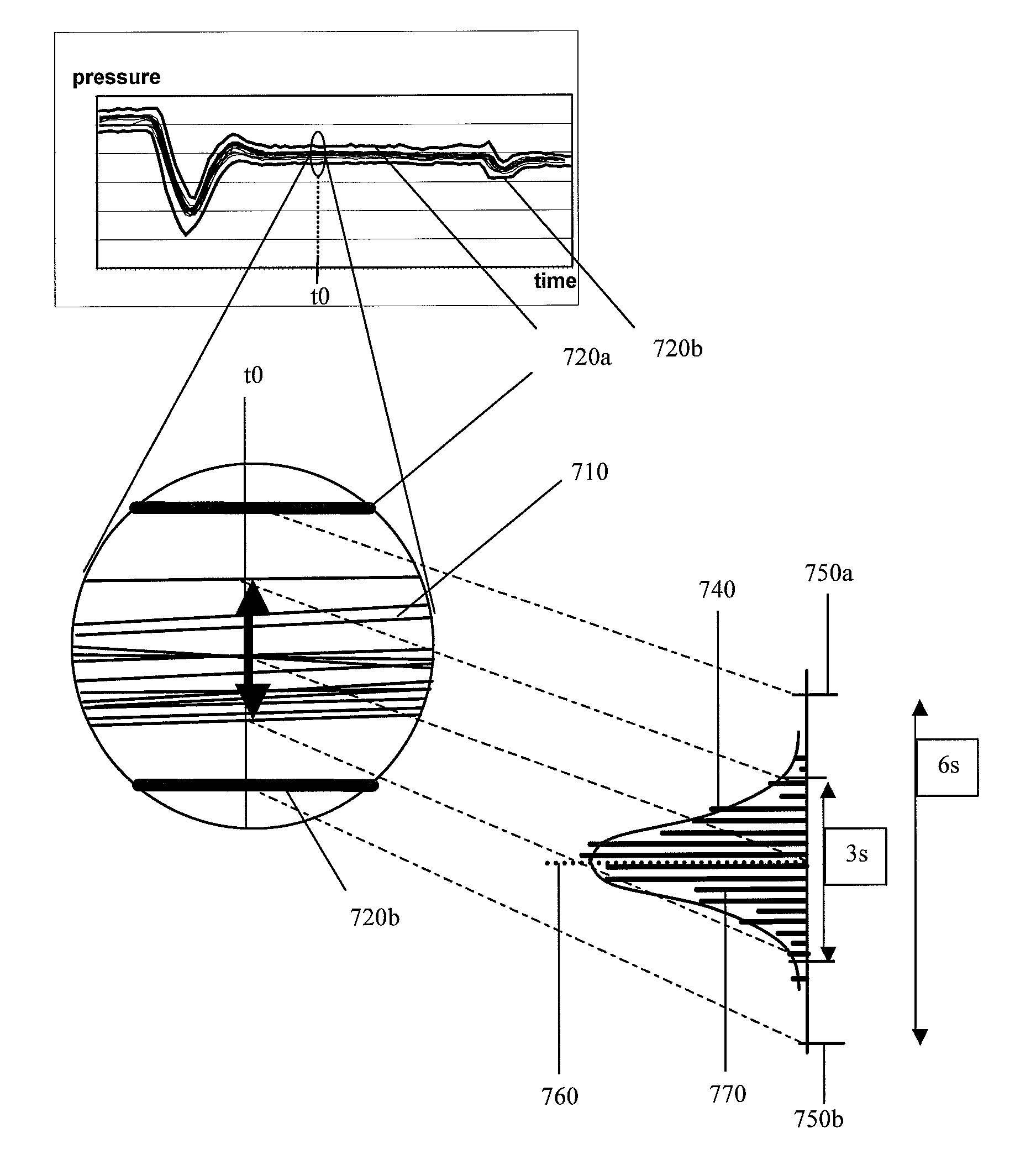
[0016]In one embodiment, the method uses interpolation points derived from a probability function, the probability function being provided by combining a plurality of test runs, i.e. by statistically combining a family of pressure curves of the same or of a similar fluid transfer process. The interpolation points are aligned with or are based on the probability function as a function of process time for a predefined, constant statistic parameter of the probability function, e.g. variance.

[0017]The present invention allows precise error detection in a fluid transfer process at a reduced storage and processing complexity by comparing the pressure with an allowable pressure profile defined by interpolation points specific to process phases of the fluid transfer process. In this way, the definition of the allowable pressure profile is adapted to the properties of the respective shape of the limit curve. In the same way, the interpolation points defining the allowable pressure profile ar...


PUM


Abstract

The present invention relates to a method for monitoring a fluid transfer process, including the steps: providing an allowable pressure profile; detecting a pressure occurring in the course of the fluid transfer process; comparing detected pressure with the allowable pressure profile and signaling an error, if the detected pressure is not within the allowable pressure profile. The allowable pressure profile is defined by interpolation points, the interpolation points being based on a probability function representing a family of pressure courses of a plurality of fluid transfer processes. The allowable pressure profile can be divided into at least two distinct process sections, each section corresponding to a distinct process phase of the fluid transfer process. The probability function is calculated from a family of test pressure curves and reflects the statistical behavior of the pipette system. The present invention further relates to a computer readable medium for storing interpolation point information as well as to a kit-of-parts comprising a device implementing the inventive method, together with a computer readable medium for storing interpolation point information.

Description

CROSS-REFERENCES TO RELATED APPLICATIONS[0001]The present application claims the benefit of EP Appl. No. 07016732.5 filed Aug. 27, 2007, the entire contents of which is hereby incorporated herein by reference in its entirety.FIELD OF THE INVENTION[0002]The present invention relates to a method for monitoring the transfer of fluid, in particular gas, by observing the pressure of the fluid. Further, the present invention relates to a method for monitoring the operation of the pipette.BACKGROUND OF THE INVENTION[0003]Volume transfer and flow velocity can be verified by monitoring the pressure in a device for transferring fluid. In the technical field of pipette systems it is known to monitor the pressure of a gas volume in the pipette filled with liquid, wherein the liquid seals the gas volume.DESCRIPTION OF PRIOR ART[0004]The application WO 02 / 073215 A2 discloses a method to evaluate a liquid dosing process in a container which is at least partially filled with gas. The temporal cours...

Claims


Application Information

Patent Timeline
Patent Type & Authority Patents(United States)
IPC IPC(8): G01F23/00
CPCG01N35/1016
Inventor ZIEGLER, GUENTERWENZIG, PETER
Owner ROCHE MOLECULAR SYST INC
Why Eureka
Try Eureka