Wire bonding deflector for a wire bonder

a wire bonding deflector and wire bonding technology, which is applied in the direction of soldering apparatus, manufacturing tools,auxillary welding devices, etc., can solve the problems of high temperature required for copper ball formation oxide formation, relatively high cost of gold, and difficult to achieve high-speed wedge bonding of wire bonding

Active Publication Date: 2011-04-05
NAT SEMICON CORP
View PDF23 Cites 16 Cited by
  • Summary
  • Abstract
  • Description
  • Claims
  • Application Information

AI Technical Summary

Benefits of technology

[0005]In a first aspect, an embodiment of the invention describes method for high-speed wired bonding. The method involves positioning a distal end of a wire-bonding capillary near a first bonding site. Extruding a length of bonding wire from an aperture in the end of the capillary. Imposing a movable deflector against the extruded length of bonding wire to bend the bonding wire to form a bent portion at an end of the bonding wire. Moving the bent portion of the bonding wire into contact with first bonding site. Wedge bonding the bent portion of the bonding wire with the first bonding site. In one approach, the wedge bonding can comprise, compressing and/or ultra-sonic bonding the bent portion of the bonding wire between the bonding site and a facing surface of the capillary and ultrasonically bonding the bent portion of the bonding wire to the first bonding site. To further continue an example method, the capillary can be moved away from the first bonding site toward a second bonding site where another end of the bonding wire is wedge bonded to the second bonding site to establish a wire bond connection between the first and second bonding sites.
[0006]In another aspect, embodiments of the invention include a wire bonding apparatus comprising a support for holding wire bonding substrates, a wire bonding capillary with an aperture for carrying and extruding bond wire and enabling bond wire attachment to wire bonding substrates, a movable deflector element arranged to enable movement of the deflector element to bend an extruded length of bonding wire such that the bent extruded length of bondin

Problems solved by technology

However gold is relatively expensive.
However, at the high temperatures required for copper ball formation oxide formation is a common problem.
The problem is quite pronounced as copper oxides are insulating materials that have proven difficult to bond.
Additionally, deformation of the electrical connections made at high temperatures lead to reliability issues.
This comes with its own set of problems.
Similar oxide formation issues make aluminum a difficult material for ball bonding applications as well.
However, because some materials are difficult to work with using high temperature ball bonding, an alternative wedge bonding approach can be used.
A disadvantage of such prior art wedge bonding technique is that it is a comparatively slow process with average bonding speeds of the order of 2-3 bonds per second being common.
Moreover, although ball bonding and wedge bonding have been used in the industry for many years, wedge bonding has up until this point been a relatively slow process even after 30 years of use.

Method used


Image

  • Wire bonding deflector for a wire bonder
  • Wire bonding deflector for a wire bonder
  • Wire bonding deflector for a wire bonder

Examples


Embodiment Construction

[0023]Reference is made to particular embodiments of the invention. Examples of which are illustrated in the accompanying drawings. While the invention will be described in conjunction with particular embodiments, it will be understood that it is not intended to limit the invention to the described embodiments. To contrary, the disclosure is intended to extend to cover alternatives, modifications, and equivalents as may be included within the spirit and scope of the invention as defined by the appended claims.

[0024]Aspects of the invention pertain to methods and apparatus for enabling high speed wedge bonding in semiconductor wire bonding applications.

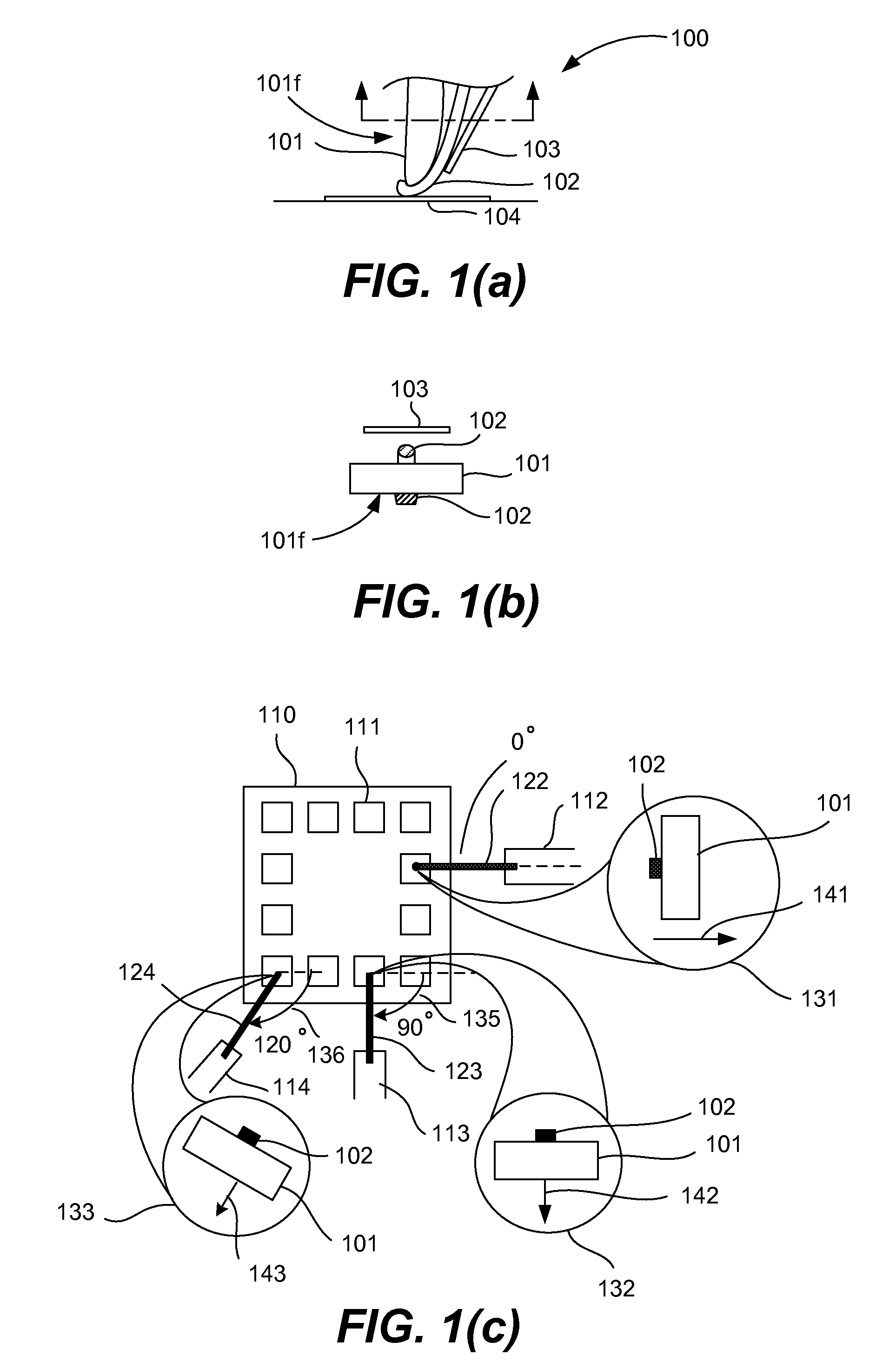
[0025]The diagrammatic illustrations of FIGS. 1(a)-1(c) provide an understanding of some of the problems inherent in state of the art wedge bonding technologies. FIG. 1(a) is a diagrammatic side view of a portion of a wedge bonding tool 100. A bond head 101 feeds a bonding wire 102 downward and can use a guide 103 to help position the ...


PUM

PropertyMeasurementUnit
Angleaaaaaaaaaa
Angleaaaaaaaaaa
Lengthaaaaaaaaaa

Abstract

Methods and systems are described for enabling the efficient fabrication of wedge-bonding of integrated circuit systems and electronic systems.

Description

TECHNICAL FIELD[0001]The present invention relates generally to semiconductor device packaging and interconnection technologies. In particular wedge bonding technologies are discussed. More particularly, apparatus, methods, software, hardware, and systems are described for achieving high-speed wedge bonding of wire bonds.BACKGROUND OF THE INVENTION[0002]In the field of semiconductor packaging, wire bonding can be used to interconnect integrated circuits and other associated components together. In particular, two main modes of wire bonding are in common usage. Ball bonding and wedge bonding. Both methods are well known in the art and have been in use for many years. As is known, ball bonding is commonly known and is frequently used with gold materials. However gold is relatively expensive. Additionally, such gold ball bonding requires surface plating (for example using silver) and heat to maintain good adhesion to bond pad materials. Additionally, attempts have been made to use ball...

Claims


Application Information

Patent Timeline
IPC IPC(8): B23K37/00
CPCB23K20/005H01L24/78H01L24/85B23K2201/40H01L2224/85099Y10S228/904H01L2224/45144H01L2224/45124H01L2924/01033H01L2924/01006H01L2224/78301H01L2224/48472H01L2924/14H01L2924/01082H01L2924/01079H01L2924/01078H01L2924/01074H01L2924/01047H01L2224/49171H01L2224/78302H01L2224/85H01L2924/01005H01L2924/01013H01L2924/01029H01L2924/00B23K2101/40H01L24/48H01L24/49H01L2224/05554H01L2224/05599H01L2224/45015H01L2224/45147H01L2224/78621H01L2224/78631H01L2224/85205H01L2224/85207H01L2224/85399H01L2924/20759H01L2924/00014H01L2924/20751H01L2924/20755H01L2924/20756H01L2924/20757H01L2924/20758H01L2924/2076H01L2924/2075H01L2924/20754H01L2924/20752H01L2924/20753
Inventor PHAM, KEN
Owner NAT SEMICON CORP
Why Eureka
Try Eureka