Encryption operating apparatus

a technology of operating apparatus and encryption, applied in the direction of digital transmission, instruments, generating/distributing signals, etc., can solve the problems of modular exponentiation, time-consuming, and less secur

Inactive Publication Date: 2011-04-05
KK TOSHIBA
View PDF13 Cites 3 Cited by
  • Summary
  • Abstract
  • Description
  • Claims
  • Application Information

AI Technical Summary

Problems solved by technology

Although this form allows faster decryption an signing by using CRT, it is less secure since it enable fault-based analysis.
The fault-based analysis is an attack method of inducing faults, which means unexpected environmental conditions for example high temperature, unsupported supply voltage or current, excessively high overclocking and etc. to reveal their internal secret data.
However, the technique disclosed in JP-A 2005-165290 (KOKAI) has a problem in that modular exponentiation concerning the check process becomes additionally necessary and this takes time, although the technique can cope with a fault-based attack.

Method used


Image

  • Encryption operating apparatus
  • Encryption operating apparatus
  • Encryption operating apparatus

Examples


first embodiment

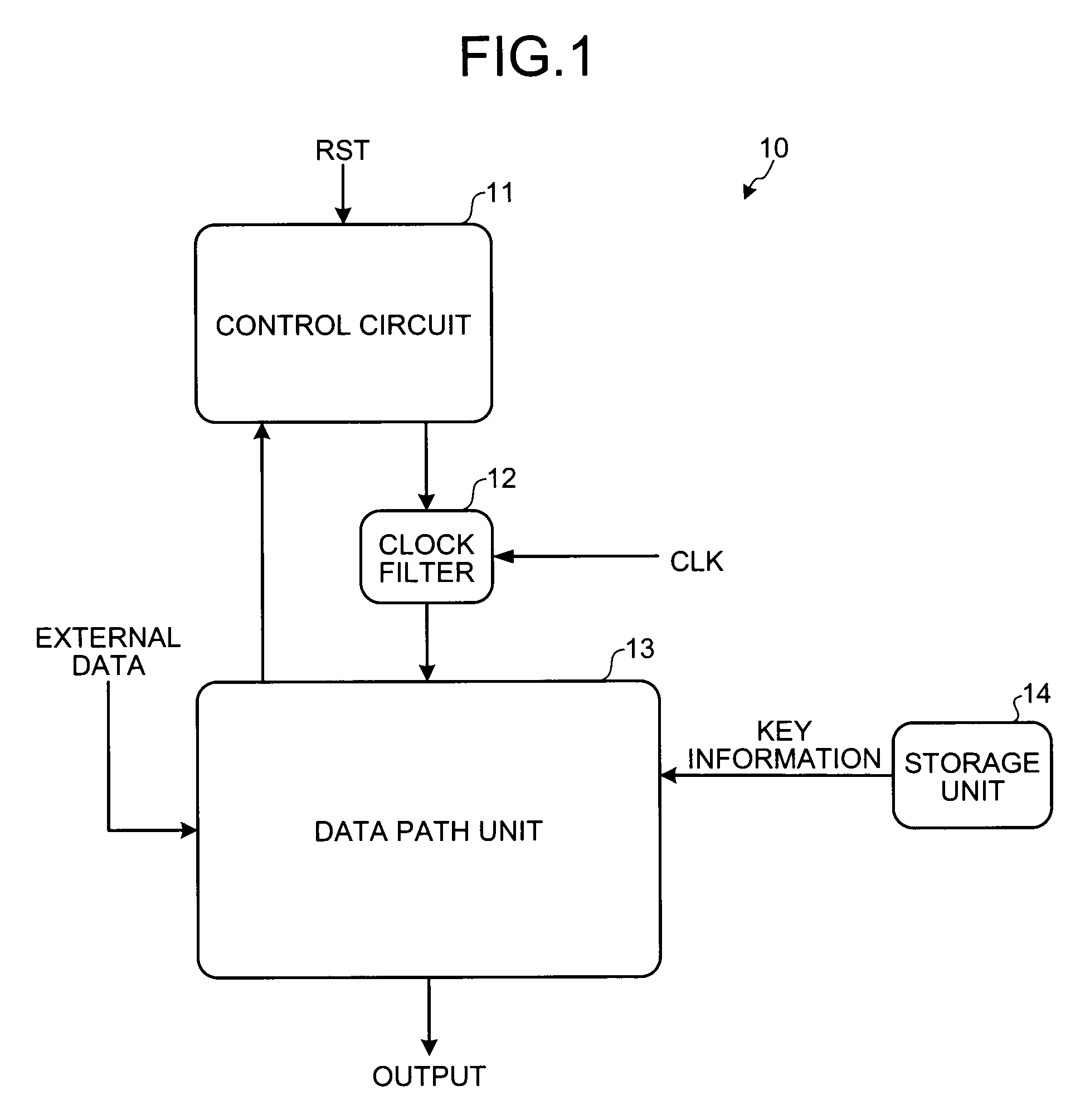
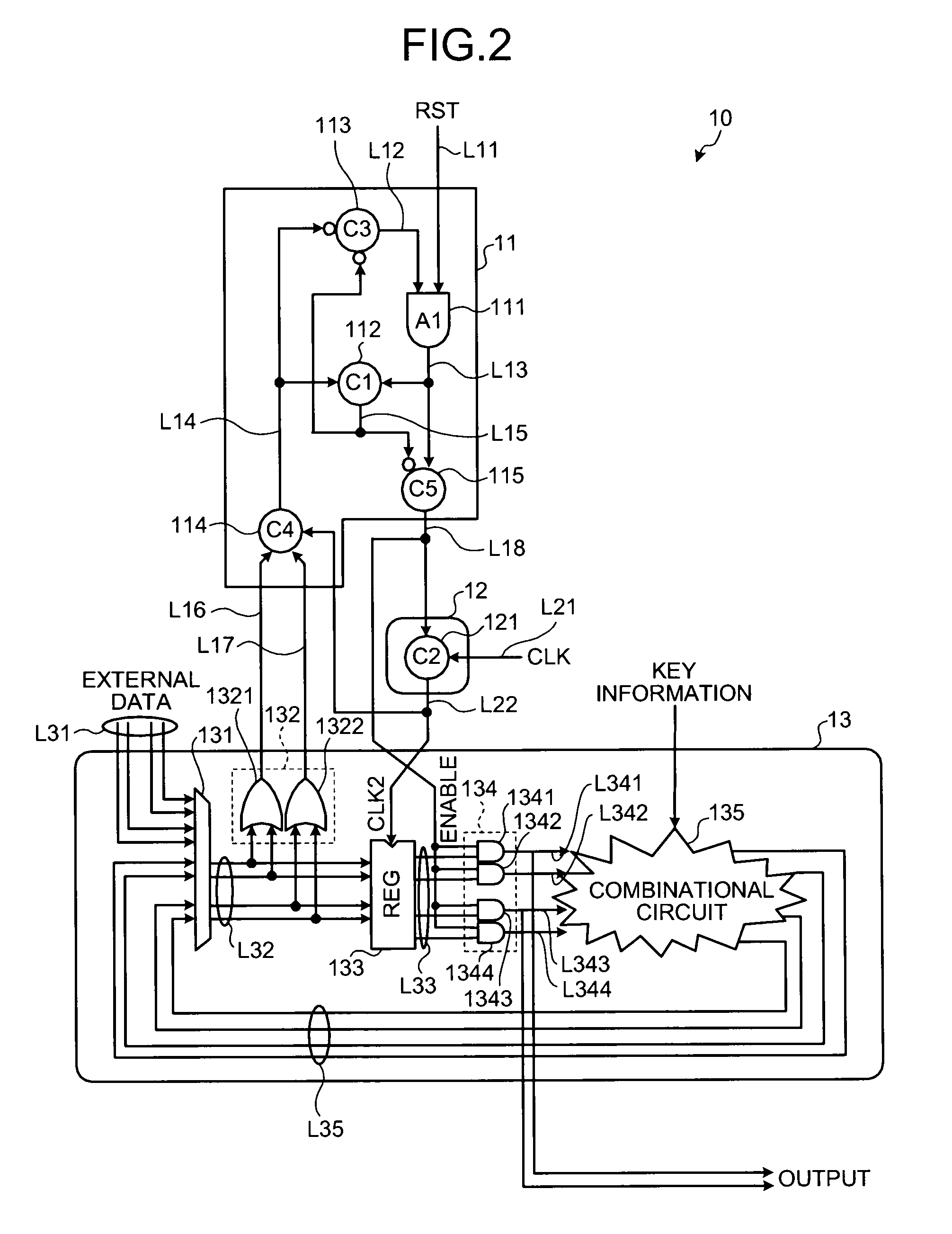
[0026]FIG. 1 is a block diagram schematically illustrating a configuration of an encryption operating apparatus 10 according to the present invention. FIG. 2 is a diagram illustrating one example of a architecture of the encryption operating apparatus 10. The architecture of the encryption operating apparatus 10 is explained below with reference to FIGS. 1 and 2.

[0027]The encryption operating apparatus 10 includes a control circuit 11, a clock filter 12, a data path unit 13, and a storage unit 14.

[0028]The control circuit 11 is a state machine circuit that monitors a state of a data value flowing through a signal line L32, and changes a state of the data value output to the clock filter 12 and the data path unit 13 each time when the signals are determined to be stable. The “signals are stable” in this case mean that the data flowing through the signal line L32 is not in the course of being changed. More specifically, this means that conduction of valid code data or invalid code dat...

second embodiment

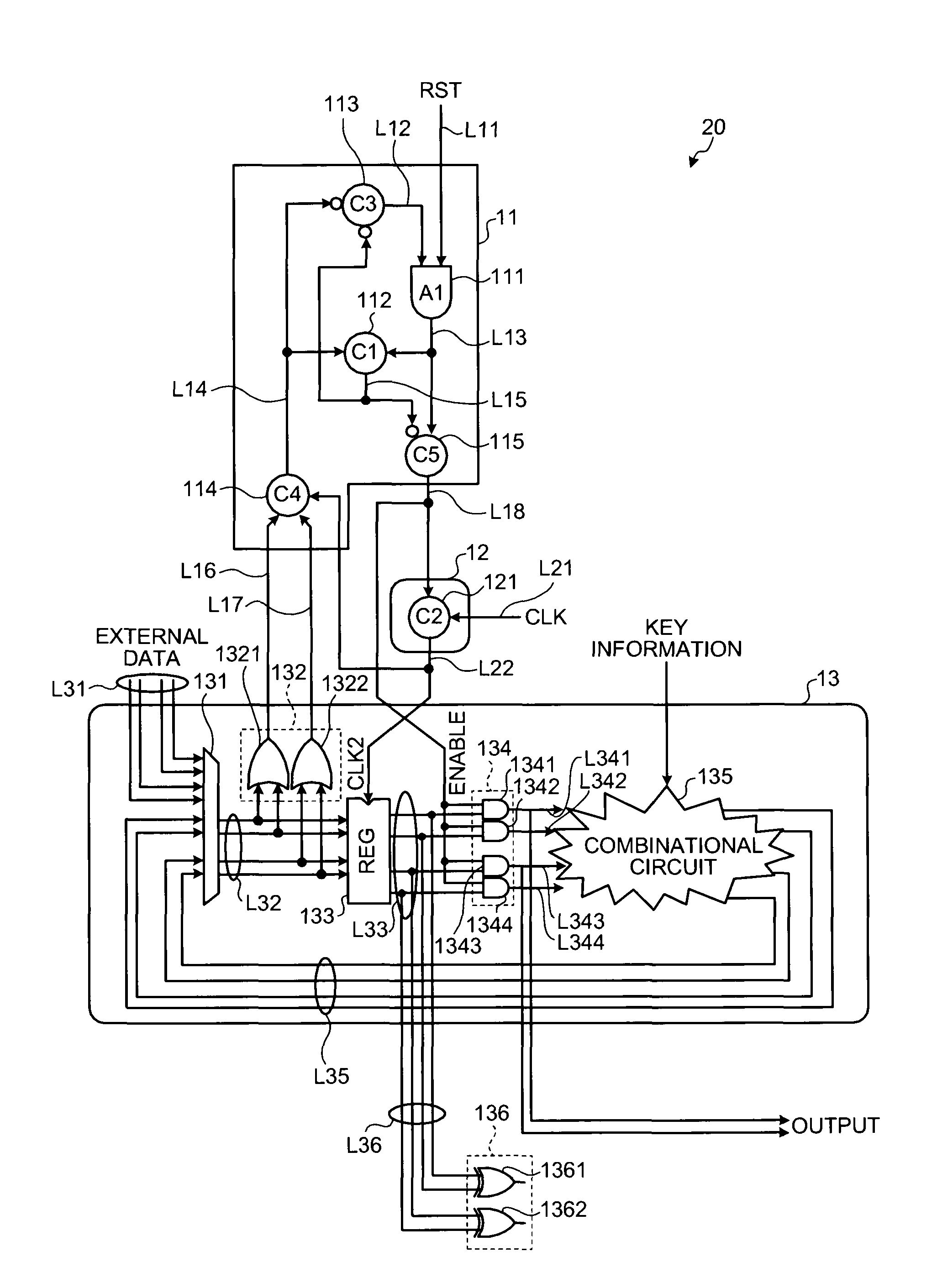
[0074]As shown in FIG. 7, in the encryption operating apparatus 20 a signal line L36 is connected to each signal line L33, and a data value latched by the register 133 via the signal line L36 is input to the detecting circuit 136.

[0075]The detecting circuit 136 includes XOR gates (1361 and 1362). Data values flowing through two signal lines becoming a pair of the signal lines L33 are input to the input terminals of the XOR gates 1361 and 1362. Detection of the invalid data is performed based on the data values output from the XOR gates 1361 and 1362.

[0076]Specifically, when the invalid data (0, 0) and (1, 1) are latched by the register 133, the XOR gate 1361 (or the XOR gate 1362) outputs the data value “0”. Therefore, when “0” is output from the detecting circuit 136, it can be determined that an error occurs in the data path unit 13 (the encryption operating apparatus 20).

[0077]As described above, according to the second embodiment, even when a fault-based analysis attack applyin...


PUM


Abstract

Valid code data and invalid code data are alternately input to a register that fetches data synchronously with a clock signal. A state of a data value input to the register is monitored. Each time when it is determined that the data is stabilized by the valid code data, the register holds the valid code data.

Description

CROSS-REFERENCE TO RELATED APPLICATIONS[0001]This application is based upon and claims the benefit of priority from the prior Japanese Patent Application No. 2007-188696, filed on Jul. 19, 2007; the entire contents of which are incorporated herein by reference.BACKGROUND OF THE INVENTION[0002]1. Field of the Invention[0003]The present invention relates to an encryption operating apparatus that encrypts and decrypts data.[0004]2. Description of the Related Art[0005]As a technique of encryption or digital signature of message, a public key cryptography is used. Although the public key cryptography has a larger amount of operation than common key cryptography, when transmitting and receiving the enciphered message, there is an advantage that it is not necessary to share a key. Therefore, the public key cryptography is widely used and various methods are proposed, such as RSA cryptography, Rabin cryptography, ElGamal cryptography, and Elliptic curve cryptography.[0006]In the public key ...

Claims


Application Information

Patent Timeline
Patent Type & Authority Patents(United States)
IPC IPC(8): H04L9/00
CPCG09C1/00H04L9/004H04L9/302H04L2209/12
Inventor FUJISAKI, KOICHIMIYAKE, HIDEYUKI
Owner KK TOSHIBA
Why Eureka
Try Eureka