Separator for separating windings

a separation device and winding technology, applied in the direction of maintaining the distance between parallel conductors, electric cable installations, transportation and packaging, etc., can solve the problems of increasing the exposed surface area of the windings, and achieve the effect of increasing the thickness of the separator, reducing the size of the apparatus, and adding to the bulk of the apparatus

Active Publication Date: 2011-04-12
CUMMINS GENERATOR TECH LTD
View PDF7 Cites 0 Cited by
  • Summary
  • Abstract
  • Description
  • Claims
  • Application Information

AI Technical Summary

Benefits of technology

[0008]Constructing a separator from a matrix of rods can allow the separator to have holes passing through the plane of the separator. This can allow air gaps to be present between groups of windings, which may increase the exposed surface area of the windings. In addition, air may pass through the plane of the separator, thereby allowing greater air flow through the windings. This may improve the cooling efficiency of the apparatus.
[0010]Preferably the rods are connected by a plurality of joints. A joint may have a narrower cross-section than a rod. A joint may be integrally formed with a rod, preferably from the same material. This may allow the separator to be manufactured simply and conveniently.
[0017]Preferably the rods are compressively rigid. This may help to ensure that the groups of windings remain physically separated.
[0020]The tag may be connected to the separator by means of a flexible joint, which may allow the tag to bend into a position where it can adhere to a suitable surface. Alternative, the tag may be formed integrally with a rod, which may provide a stronger connection. The tag may be formed with its upper or lower surface in the same plane as the bottom of the separator, which may avoid the need to bend the tag.
[0026]The thickness of the air gaps is determined partially by the thickness of the separator, and thus a relatively thick separator is desirable from the point of view of good electrical separation. However it is normally preferable to minimize the size of the apparatus, and increasing the thickness of the separator may add to the bulk of the apparatus. Thus the thickness of the separator is preferably sufficient to ensure electrical separation of the groups of windings, while at the same time avoiding adding unnecessary bulk to the apparatus.
[0027]The thickness of the air gaps is also partially determined by the size of the cells. This is because some drooping of the windings into the air gaps may take place, thereby reducing the size of the air gaps. The larger the size of a cell the more likely it is that windings will droop into the air gap. However, at the same time it is desirable for the cells to be as large as possible to allow greater air flow through the windings. Thus the cells are preferably small enough to ensure electrical separation of the groups of windings, while at the same time large enough to provide effective cooling.

Problems solved by technology

This can allow air gaps to be present between groups of windings, which may increase the exposed surface area of the windings.

Method used


Image

  • Separator for separating windings
  • Separator for separating windings
  • Separator for separating windings

Examples


Embodiment Construction

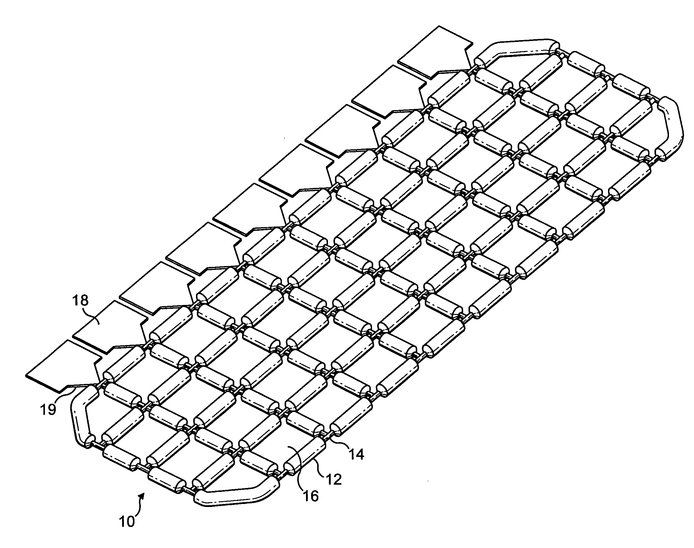
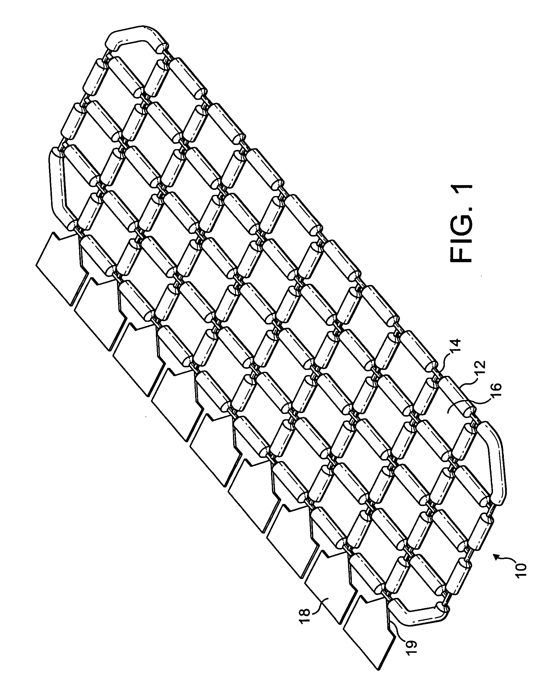
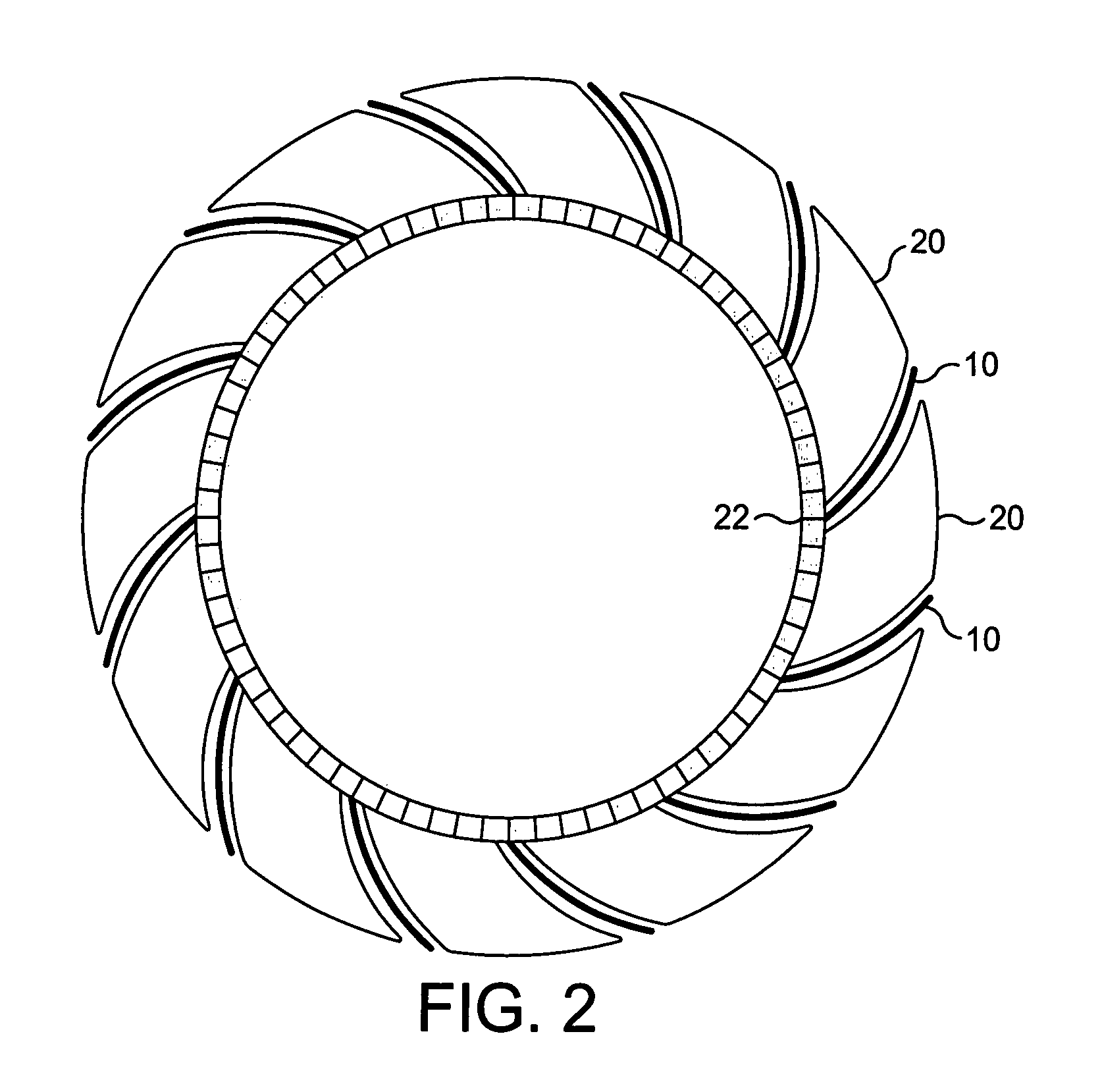
[0038]An embodiment of the present invention relates to a separator for separating groups of windings in an electrical machine such as a generator or motor. In such a machine the stator is normally wound with a number of groups of windings. Normally the number of groups of windings is equal to the number of poles times the number of phases. For example, the stator of a four-pole, three-phase machine may carry twelve groups of windings. In order to achieve a compact design, the groups of windings often overlap with each other.

[0039]In a rotating electrical machine the stator normally acts as the armature and carries the main electrical power. Since windings of different phases may overlap with each other, considerable electrical potential may be present between overlapping groups of windings. This creates the need to separate groups of windings electrically. Previously this has been achieved by providing a layer of composite paper between groups of windings, or substantially increasi...


PUM

PropertyMeasurementUnit
temperaturesaaaaaaaaaa
thicknessaaaaaaaaaa
thicknessaaaaaaaaaa

Abstract

A separator is disclosed which provides an electrically insulating layer between groups of windings in an electrical apparatus, such as a rotating electrical machine. The separator comprises a matrix of interconnected rods. This can allow air gaps to be present between groups of windings, which may improve the cooling efficiency of the apparatus.

Description

BACKGROUND TO THE INVENTION[0001]The present invention relates to a separator for separating windings in an electrical apparatus.[0002]Electrical apparatuses such as motors, generators and transformers generally comprise electrical windings wound on an iron core. The individual wires in the windings are electrically insulated by means of an outer insulation layer, which is typically enamel. However faults may develop in the outer insulation layer either due to the manufacturing process, or due to stresses imposed on the wires during construction or use of the apparatus.[0003]Many electrical machines are constructed with overlapping groups of windings. For example, in a three phase motor or generator each phase many have one or more groups of windings, and each group may overlap another group. In such a machine, overlapping groups of windings may be at different electrical potentials. Any faults in the insulation in the wires could then lead to arcing between the groups. This would m...

Claims


Application Information

Patent Timeline
Patent Type & Authority Patents(United States)
IPC IPC(8): H02G7/12B65H81/06
CPCH02K3/34
Inventor MADDISON, CHRISTOPHER PAULRILEY, MARK JASONSHANEL, MARTINSAUNDERS, JOSEPH WILLIAMHANWELL, PETER FRANCISGEE, ADRIAN NORMAN
Owner CUMMINS GENERATOR TECH LTD
Why Eureka
Try Eureka