Method for controlling polyphase rotating electrical machine

a technology of rotating electrical machines and electrical machines, which is applied in the direction of electrical apparatus, electronic commutators, ac motor stoppers, etc., can solve the problems of high network output and prove inacceptabl

a technology of rotating electrical machines and electrical machines, which is applied in the direction of electrical apparatus, electronic commutators, ac motor stoppers, etc., can solve the problems of high network output and prove inacceptabl

US7923949B2Inactive Publication Date: 2011-04-12VALEO EQUIP ELECTRIC MOTEUR

Image

  • Method for controlling polyphase rotating electrical machine
  • Method for controlling polyphase rotating electrical machine
  • Method for controlling polyphase rotating electrical machine

Examples


Embodiment Construction

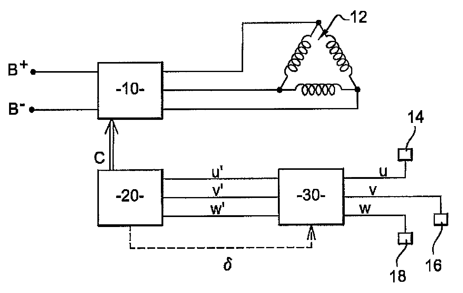
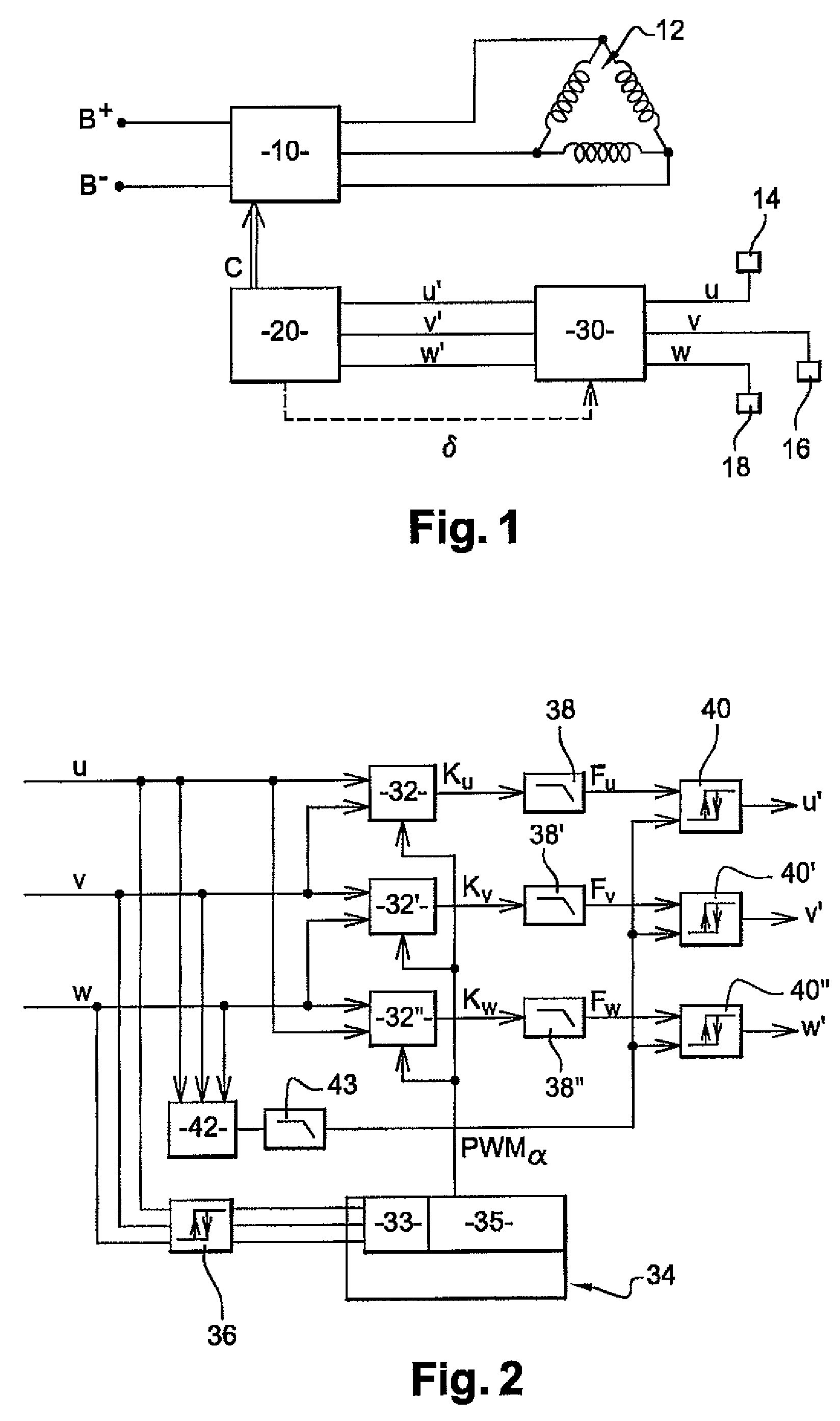
[0035]FIG. 1 depicts the essential elements of the electrical circuit of a polyphase rotary electrical machine, for example reversible of the alternator starter type.

[0036]Such a machine comprises a power bridge 10 that supplies the three phases of a three-phase stator 12 from a voltage generated between the two terminals B+, B− of supply battery.

[0037]The power bridge 10 is formed by switches (not shown) that are controlled by control signals C so that the various windings of the stator have signals passing through them offset by 120° with respect to one another.

[0038]The control signals C are generated by an electronic control module on the basis of signals U, V, W issuing from three linear sensors 14, 16, 18 equally distributed over the circumference of the rotary machine.

[0039]Precisely, the signals U, V, W issuing from the sensors are processed by a phase lead unit 30 that delivers three signals U′, V′, W′ corresponding to the sensor signals U, V, W with a phase lead δ with res...


PUM


Abstract

A method for controlling a reversible polyphase rotating electrical machine, wherein at least one coil circuit is supplied through a bridge of switches, including the following steps: controlling (P1) the bridge to deliver to the coil circuit a periodic voltage with a phase shift (d) relative to an electromotive force induced in the coil circuit, such that an operating torque is generated, the phase shift having initially a first value (d0); controlling (P2) the bridge to deliver to the coil circuit a periodic voltage with the phase shift (d) producing a torque ranging between the operating torque and the opposite of the operating torque, the phase shift taking on a plurality of values upon the control; flipping (T2) the bridge in rectifying mode.

Description

CROSS-REFERENCE TO RELATED APPLICATIONS AND CLAIM TO PRIORITY[0001]This application relates to International Application No. PCT / FR2007 / 050617 filed Jan. 5, 2007 and French Patent Application No. 0600536 filed Jan. 20, 2006, of which the disclosures are incorporated herein by reference and to which priority is claimed.FIELD OF THE INVENTION[0002]The invention concerns a method of controlling a reversible polyphase rotary electrical machine in which at least one coiled circuit is supplied through a switch bridge, such as for example an alternator starter.PRIOR ART[0003]A rotary electrical machine conventionally comprises a rotor and a stator. One of these elements has a direct current passing through it and thus generates a constant magnetic field of fixed orientation with respect to this element. The other element comprises a plurality of distinct windings angularly spaced apart; each winding has passing through it a current offset in phase with respect to that of the other winding ...

Claims


Application Information

Patent Timeline
12 Apr 2011
Publication
US7923949B2
IPC
H02P1/40
CPC
H02P25/025; H02P6/142; H02P6/15; H02P25/034
Inventors
MASFARAUD, JULIEN; DOFFIN, HUGUES